The 1971 Panteras did not have fan relays mounted near the fan motors like the later cars. All of the power for the fans is provided by a relay that is located under the dash on the passenger side. Some of the 1971 cars did not even have thermostatically controlled fans or might have one fan thermostatically controlled and one fan controlled by the fan switch on the dash. The best way to power high current fans is to place the relays close to the fans and provide a large gauge wire directly from the battery to the relays.
My car, like many Panteras has the fan wiring modified so that both cooling fans are thermostatically controlled and a third fan is installed behind the radiator that is manually controlled by the dash fan switch. The car also has a aftermarket dual pass radiator with two separate tanks on the passenger side. The third fan and dual pass radiator was a popular cooling system modification in the 80s.
The existing configuration of the cooling system on my car works fine but I decided that it would be nice to have some extra stock fans that I could rebuild and have as spares. I found some used fans with shrouds and discovered that one of the fan motors was a like new, high power, Kysor unit. The Kysor motor is about 1/3 longer than the stock Lucas motors and has a longer armature and magnets. It really moves some air compared to the stock fan!
I started to do the Mike Drew fan relay mod to my car last year and discovered that on my car the fans are not powered through ignition switch like the later cars. But, I did want to add fan relays near the fans and finding the high power Kysor fan was just the incentive I needed. I think stock fans will also benefit from the relays and higher current availability because my stock fan is running faster, just with the new wiring. The old wiring was pretty small and I'm sure is was dropping some voltage.
I decided that I would add the 30 amp relays in the same location as the relays on the 1972 and later Panteras and that I would tap the power for the fans directly from the battery. But at the same time I did not want the fans to run with the ignition turned off. I used a inline 30 amp fuse that is located next to the battery. Tapping directly off the battery is a common way to power high powered fans. Be sure to disconnect the battery while doing this work!
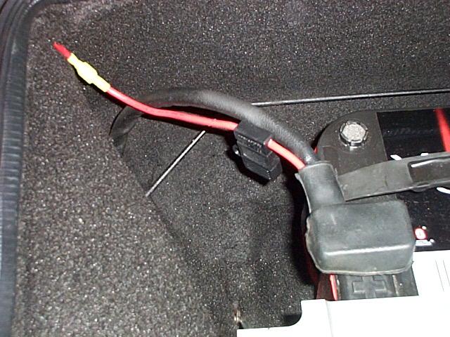
The inline fuse has a connecter crimped on the battery end and is attached to the battery positive lead connecter bolt. The other end has a connecter that attached to the #10 wire that feeds to the relays. The fuse has #10 wire leads. The inline fuse is a RadioShack part number 270-1234. The inline fuse holder uses the modern spade type fuse and has a neat plastic cover. I was able to route the #10 power wire under the trunk felt and right next to the weather strip along the passenger side of the car.
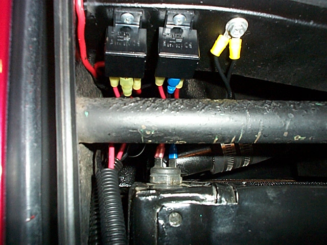
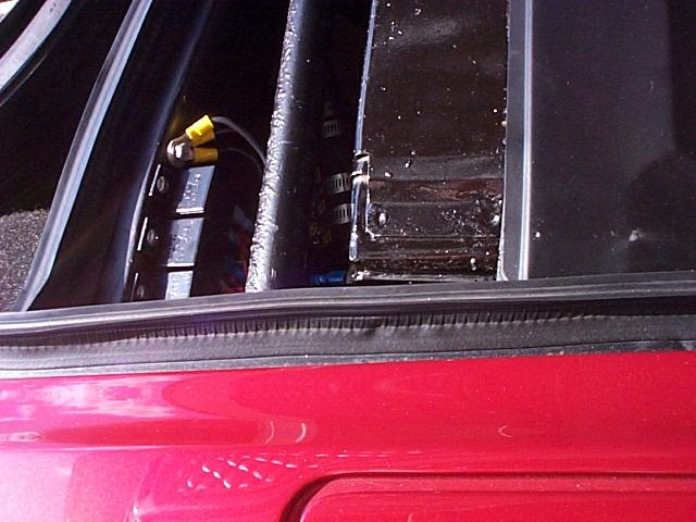
The relays mount in the stock position for the 1972 cars. I used RadioShack 30 amp relays, part number 275-226. I'm sure there must be better relays available but the RadioShack units seem to work OK. Be careful when sliding the large wire connecters on the relay spade connectors, because too much force can push the spades into the relay case and damage the relay. The view above shows the two relays mounted and the ground returns for the fans can be seen next to the relay. In the above image on the left, the relay on the left, has #10 yellow connectors on the relay coil terminals and were used to loop the existing fan power to the two relays. The main 12v power lead (#10 wire) to the two relay power terminals was split into a "Y" connection using #12 wire. The joint was made by using a covered butt joint terminal that was crimped to the wirers and then soldered The joint was also covered with heat shrink.

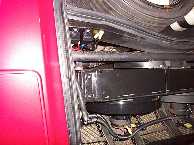
Plastic tube armor was used to route the wires from the relays to the fans.
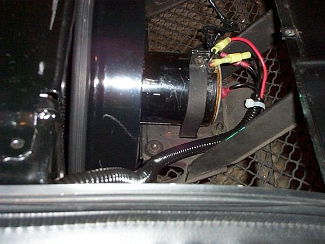
View of the fans with the fan housing cover removed and showing the route of the fan wires. Number 12 wire was used for the power feed and ground return for the power feed between the fan motors and relays. I used large size wire throughout the system to reduce the voltage drop and increase the current and voltage to the fan motors. The more voltage and current that is supplied, the faster the fans run and move more air. The yellow #10 and pink #12 connectors are available at RadioShack. I left the existing, manually controlled third fan on the back of the radiator with its existing wiring just for a backup system.
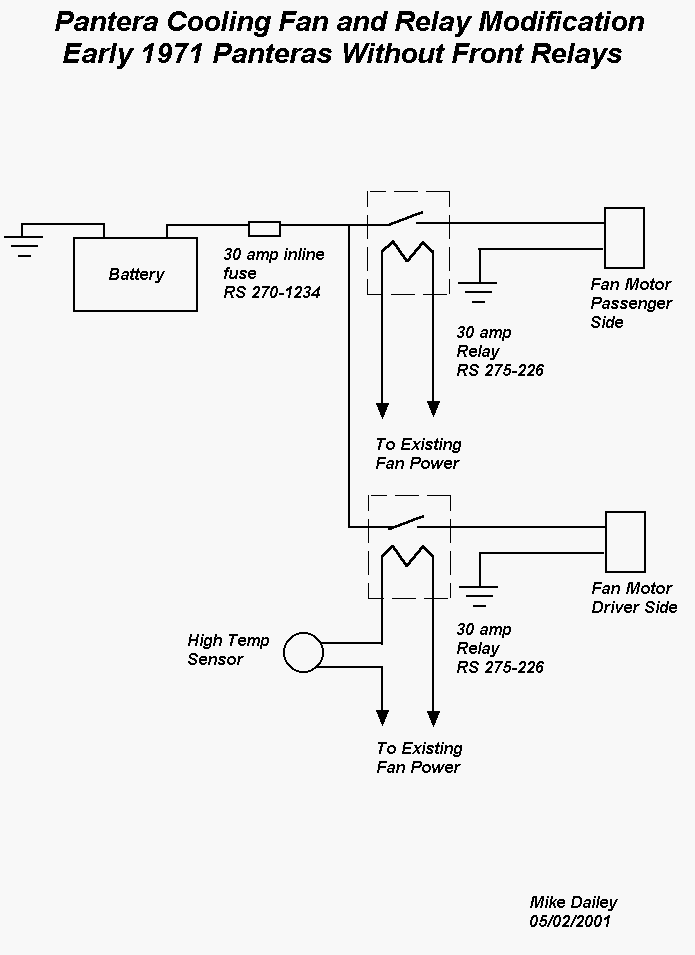
The wiring diagram
My radiator has two thermostatic switches installed in the two passenger side end tanks, the lower tank (inlet) activates around 180 degrees and the one on the upper tank (outlet) activates around 190 degrees. The degree readings I am referring to are what is indicated on the engine temp gauge when the switches activate. The existing fans were both controlled by the lower tank temp switch. The wiring diagram shows how to wire the system so the fans are sequenced for one fan on during low temp (180 degrees) and both fans run during high temp (190 degrees).
This wiring and relay system off loads all of the front fan load from the cars existing wiring and provides very high current availability to the fans. The wiring also bypasses the cars amp gauge. This causes the amp gauge to display a charging condition when the fans are running rather than a discharge because it shows the charge going into the battery from the alternator.
After installing the two relays for the two front pusher fans I decided that the third backup fan that is mounted on the back of the radiator would also benefit from a relay mounted upfront with the other relays.

Position of the third relay
I moved the two front relays further to the passenger side to make room for the third relay. The #10 power feed was split into three #12 wires using a covered butt joint splice and soldered. Number 12 wire was used for the fan power and ground return. The relay coil was connected to the original fan power leads. I do not have any way to accurately measure how much faster the fans run with the larger wire, direct power feed and new relays, but from the sound that the fans make, it sounds like they are running much faster.
After running the power for the fans directly from the battery for a few years I later changed the power source to the the #8 size wire that I had run from the AMP gauge to the fuse box area to power the headlight really mod. The headlight relay mod can be seen here.