Mike Drew published a great set of instructions on improving the Pantera lighting system by installing relays to off load the headlight power from the headlight switch and the very expensive low and high beam switch.
The following is how the installation of the relays was done on my 1971 Pantera. Be sure to disconnect the battery while doing this work!
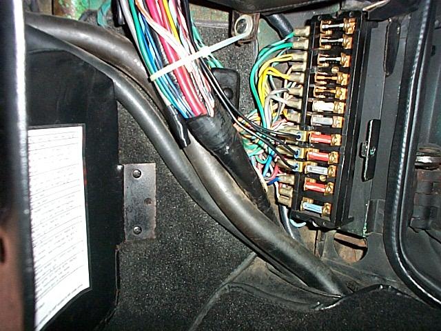
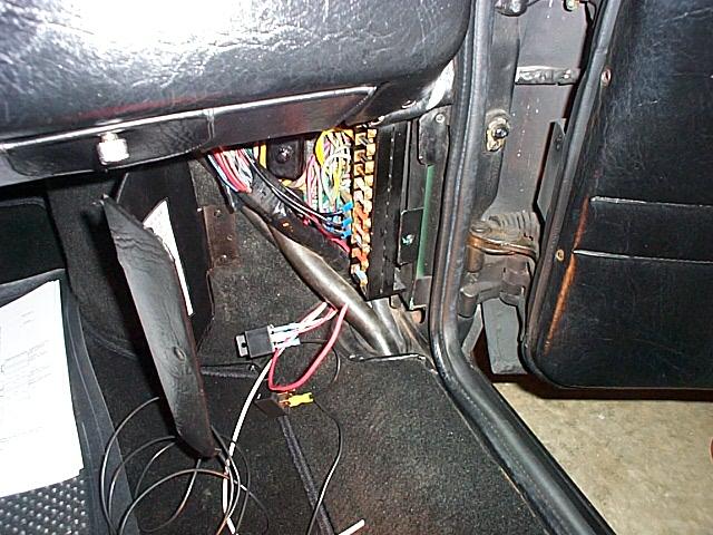
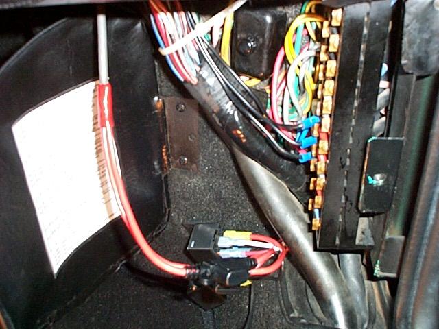
View of the fuse panel with the cover open. All of the wiring is completely stock excluding the three small black wires on fuses 8, 9 and 10 that are used for the radio and power antenna. The heavy #8 gray wire with tape on the end goes to the amp gauge and was installed last year when I first started the project.
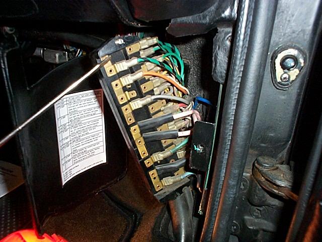
The fist step was to remove the two screws holding the fuse block and moving the fuse block out for access to the wires. The green/black wire on the (in the image it is on the left side of the 1&2 fuse bracket) 1&2 fuse and the gray wire on (in the image it is on the left side of the 5&6 fuse bracket) the 5&6 fuse were removed and connected to white #14 wires. Red #12 wires were connected to the fuse terminals where the green/black and gray wires had been terminated. Wire connectors were used for all of the connections and did not require any cutting of the original wiring.
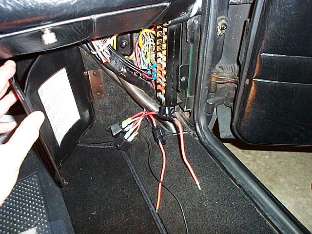
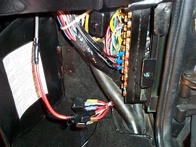
View of the white and red wire. Note how the wires are routed around the fuse block and how the white wire is connected to the green/black wire with a wire connector.
The white wire was connected to the coil of the first relay and the red wire was connected to the normally open contact of the relay. The wires from fuse 5&6 can be seen in this view and are ready to be connected to the second relay. The relays are 40 amp units from RadioShack.com and are part number 900-2394. They have a normally closed contact that was not used.
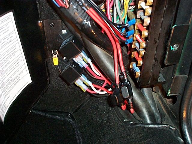
This view shows the second relay being connected. Note how the black ground wire is looped between the relay coils using connectors.
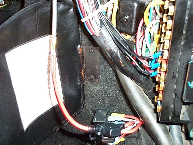
In this view all of the wires are connected to the relays and the twenty amp inline mini-fuses (the holders are rated at 30 amps) are connected to the power side of each relay. The inline fuse holders are from RadioShack.com and are part number 270-1237.
On the left side of this image you can see the gray number eight wire that is connected to the amp gauge. The inline fuse wires are connected to the number eight wire with a inline splice fitting and crimped. The inline butt terminal splice is from RadioShack.com and is part number 910-1858.
The wires are then soldered inside of the splice at both ends.
The inline splice has a red plastic cover that slides over the the splice.
I added some heat shrink over the read plastic cover for extra protection. The red plastic cover heat shrink was slid way up the gray wire out of the way before the splice was soldered.

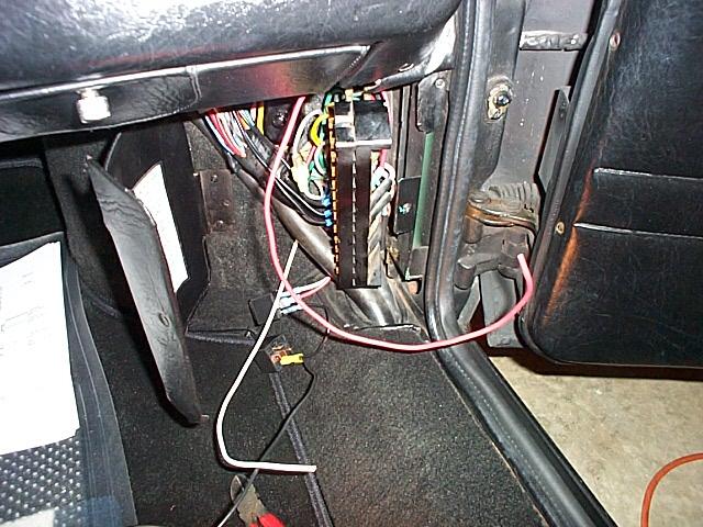
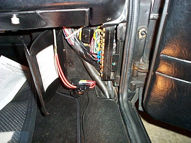
The power wire is wire tied to the wiring harness with one wire tie.
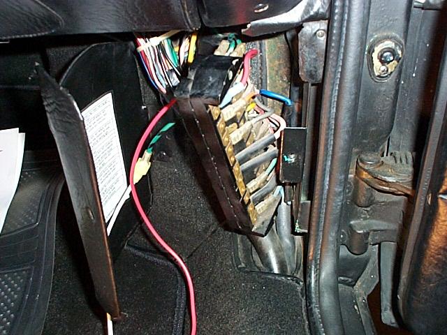
The relays are attached to the fender well and the relay ground is completed. I found that the relays had to be mounted at an angle because on 1971 cars the A/C lines take up space in the fuse area. With the fuse door cover closed all of the relay wires are well protected and covered.
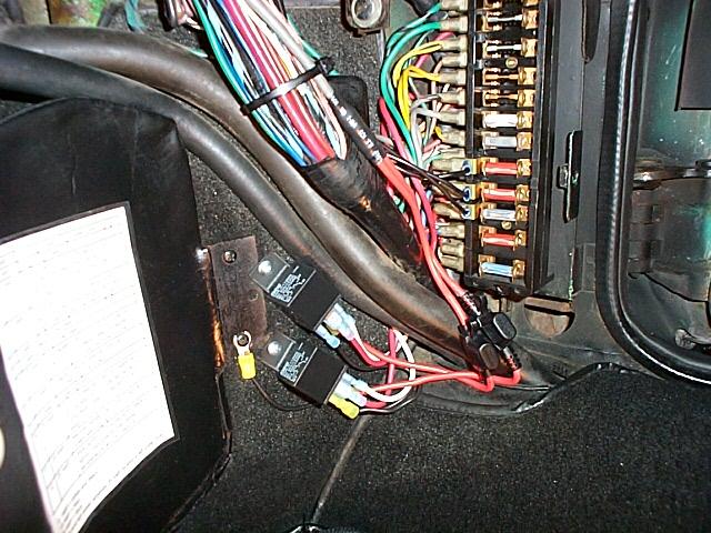
Another view of the relays and inline fuses. I'm going to add some number tags to the fuse holders and add the information to the fuse index that is on the inside of the fuse cover door. It all worked as advertised!
.