September 15, 2000 - The Overview
Some months ago there was a post on the de tomaso email forum about the stock back wheel bearings and how to check them to see if they were potentially ready to fail. Some of the posts said checking the wheel for play was a good test. But someone said that every time they had a bearing fail, the wheel would be tight, feel OK and then the bearing would suddenly fail without warning.
I’ve had a very, very small amount of play in the drivers side axle for the last two years and the passenger side has been tight. So every few weeks I’ve been checking both axles for play and found no change. I figured with the wheel play that I would most likely need to replace the axle anyhow. I’ve been deciding on what bearing solution I was going to use, so I didn’t want to pull it apart until I was ready with the new bearings. As I could not see any change in the play, even with a dial indicator, I figured that it would be OK for awhile. Wrong!
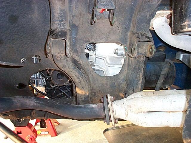
Last week I noticed an intermittent rubbing sound when I turned, like a small stone under the brake pad. It was the very inside edge of the passenger side rotor (luckily not the part where the brake pad rides) rubbing one of the caliper mount lugs on the upright. The wheel is still tight and has no play but apparently under side load the bearing is letting the axle move in so that the rotor will rub lightly on the upright. Lucky for me that the caliper is spaced so that it just misses the rotor surface when the rotor hits the upright.
One of my the major goals for my Pantera in 2000 was rebuilding the back suspension and now with the bearing failure it is a major priority. The project will include the replacement of the A arm bushings, shocks and springs, axel bearings and the half shafts. Over the last year I've be collecting the parts for the project.
I’m planning to install the new roller bearing system that Dick Koch has designed that requires no machining of the upright and has a separate seal for the outside and inside bearing.
Shocks
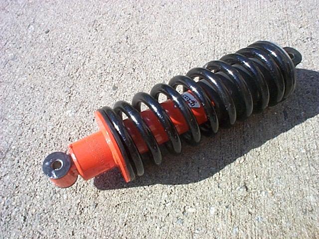
The first items that I collected were some used but almost new Koni shocks. I wanted to use the Koni shocks because they are guaranteed for life and for a street car work well. I installed the front Konis last year. The Koni shocks are no longer available new from Koni so I was lucky to find a set that are like new.
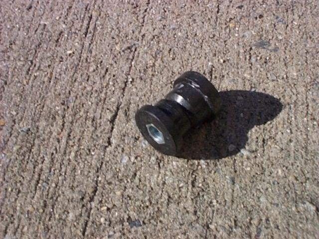
Bushings
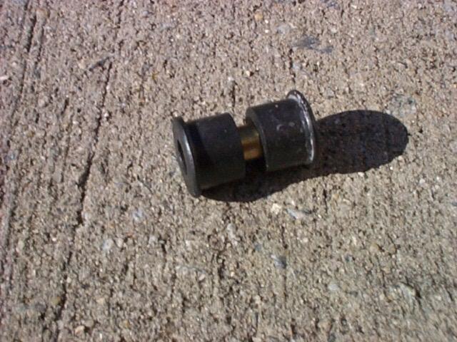
I decided to replace the Koni shock bushings to make sure the shocks would work like new. The bushing needs to be installed so that the front and back of the bushing is installed and then the mounting shaft inserted. If your try to push the bushings in with the shaft in place the anti-seize will cause air to get trapped inside and the bushing will not press in. I used a small amount NAPA auto parts anti-seize to lube the bushings before assembly..
Eight new A arm bushings were purchased from Pantera Performance for the back A arms.
Half Shafts

The car needed new half shafts because someone had spot welded one the the U joint caps in one of the yokes and some of the U joint caps were turning in the yokes. Welding the caps is not a uncommon fix for people that want a cheap but dumb fix. Spinning or turning U joint caps are a sign the the yokes bores are worn and sloppy.
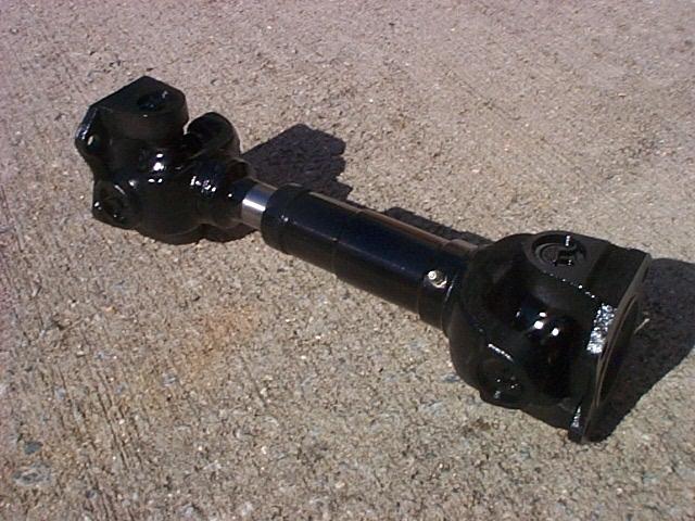
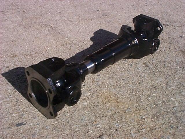
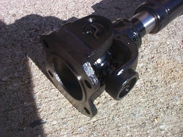
I shopped around a decided to purchase two new Spicer half shafts from PI Motorsports. The shafts come un-painted and covered with a thin coat of oil. I cleaned the oil off by wiping them with a paper towel and paint thinner and then painted them gloss black. The U joints in the PI Motorsports Spicer shafts do not have grease fittings but that's good as it makes them stronger. The yoke has the wording "Spicer" cast into the large end of the shaft.
Roller Bearings
One of the very week points of the Pantera is the rear axle bearings. Ball bearings are use to support the axle and are not very well suited to carry the loads that our big fat sticky tires can exert on them. A ball bearing is just not a good bearing for handling heavy side loads. On the Pantera, the single outside bearing carries most of the side load forces. Roller bearings are a much better solution for handling side loads and the big fat sticky tires.
Dick Koch's bearing system uses an inter and outer Timken tapered roller bearing. The roller bearings are located in about the same lateral location inside the upright that the stock ball bearings were located. The system is designed so that a separate high quality seals can be used to seal the complete bearing assembly. This was one of the many tricky parts of the design and I was able to contribute the idea for the inside seal arrangement. Dick’s system requires no machining of the upright. This appealed to me because most roller installations require machining of the upright and then you are locked into that bearing solution forever. Learn more about Timken tapered roller bearings.
Dick’s bearing setup is an assembly so the bearing system can be pre-assembled and the pre-load adjusted before the assembly is inserted into the upright and the axle installed. Pre-load is used when roller bearings are installed to adjust the amount of pressure or lack of play that is exerted on the bearing races and bearing rollers in their static state. With Dick’s design the bearing system will be available so that it is delivered ready to be installed with no adjustments other than having the axle nut torqued to spec. This also solves the problem of needing to ship your very valuable uprights some place to have them machined and bearings installed.
Dick's bearing design drawings are at the machine shop awaiting the shop to make the prototype bearing set up. When the machine shop is done we will start the next phase of removing the back suspension and get it ready for the upgrade.
October 22, 2000 - Removing The Suspension
The first bearing sleeve and spacer prototype came back from the machine shop and it looks and fits great in Dick’s up-right. Now that the prototype works my set of sleeves and spacers should be completed by the machine shop by the end of next week. The next step is removing the suspension from my car.
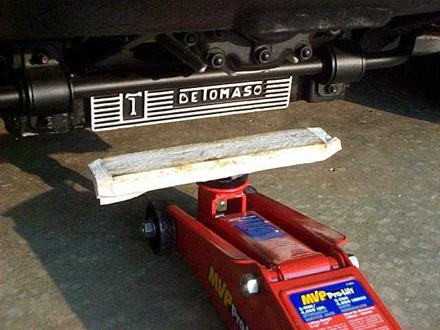
The first step is jacking up the back of the car. The back cross member is in good shape on my car so I use a wood spacer to fit under the cross member and to keep the jack from damaging the area.
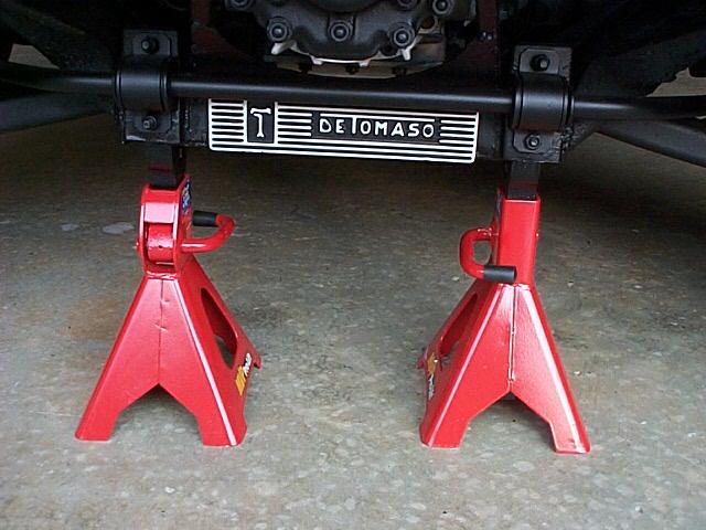
I like to position the jack stands at the back end of the frame rails to provide more room to work around the suspension.
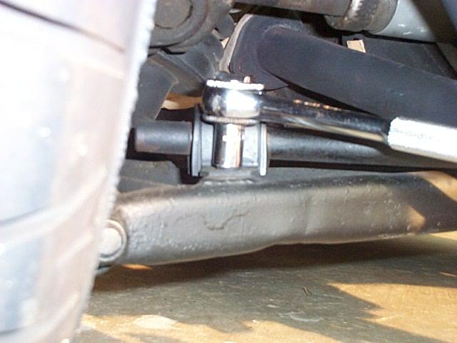
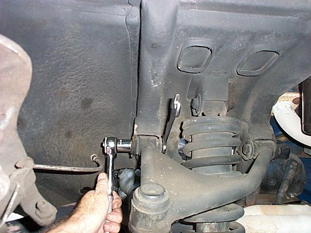
The first item to be removed is the anti-roll bar brackets on the lower A arms. You might want to do this with the car fully-jacked-up to take the tension off of the mounts.
If your car has polyurethane anti-roll bar bushings it would be a good idea to remove the anti-roll bar completely and clean the bar, bushings and mounts. I used a small amount of NAPA auto parts anti-seize to lube the inside and outside of the bushings. Un-lubed polyurethane bushings can make very bad creaking noises as the suspension moves. The front anti-roll bar is easiest to detach with the car setting on the suspension.

Next, the back wheels are removed.
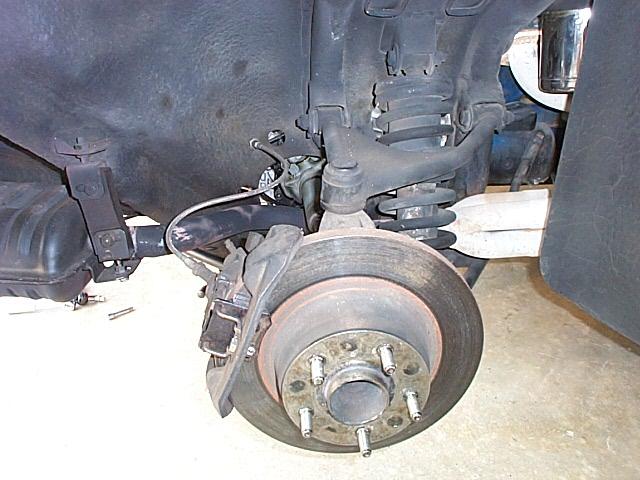
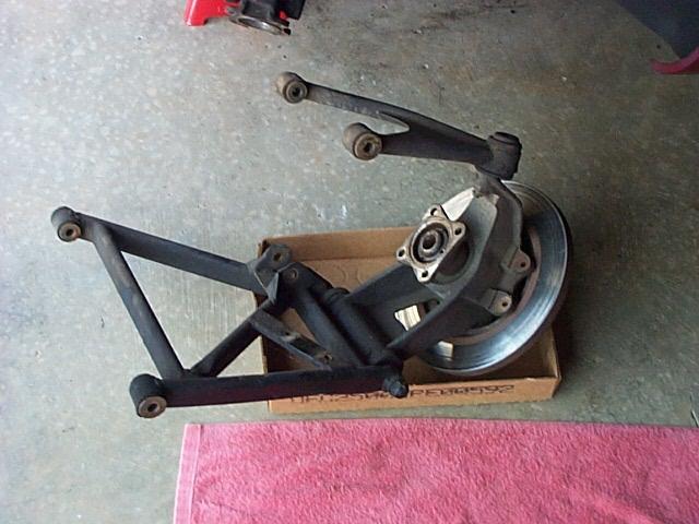
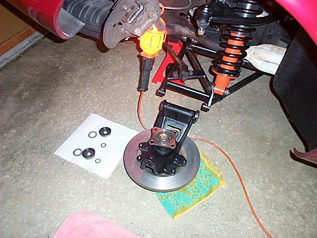
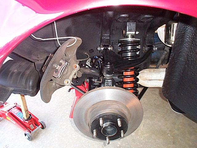
View of the back suspension with the wheel removed.
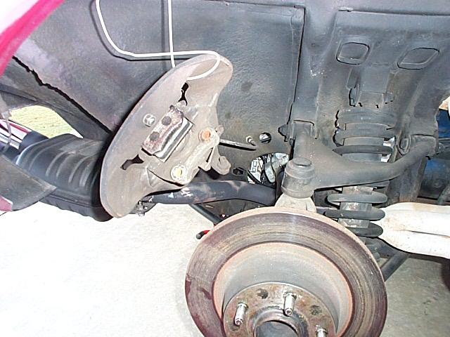
The next step is removing the two bolts holding the caliper and suspend it out of the way with a wire.
The four bolts are removed from the inside and outside half shaft mounts. The shaft is turned to gain access to the bolts and nuts.
 .
.
Next, I broke loose all of the suspension and shock nuts and bolts. Penetrating oil was applied to help release the nuts.
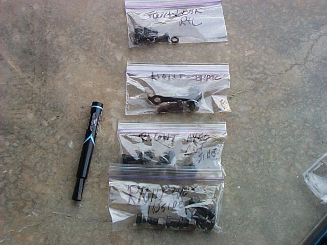
I like to put the nuts and bolts in bags and label each bag.

A jack was placed under the rotor with a pad and the suspension lifted slightly so that the shock could be removed. After the shock bolts were removed the suspension was lowered with the jack to to provide space to remove the shock. The suspension is very heavy so be careful.
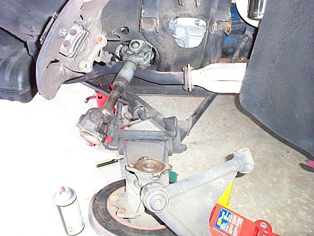
The top A arm bolts were removed and the assembly moved out and down from the top. The tail pipe to header flange bolts was backed out so that the pipe could be moved to make room to remove the half shaft.
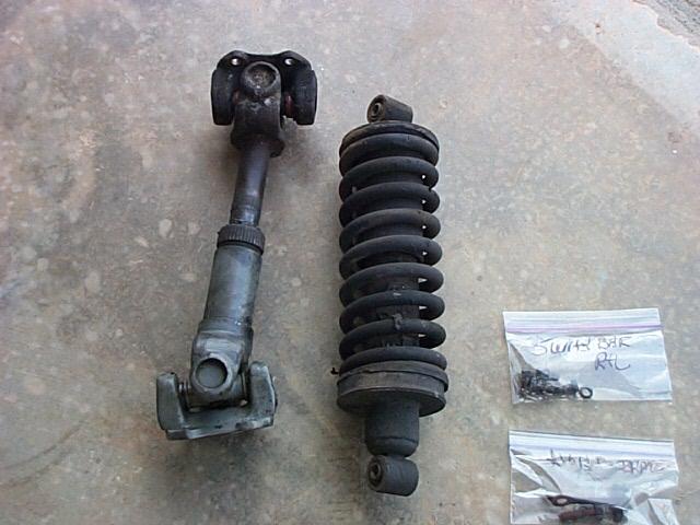
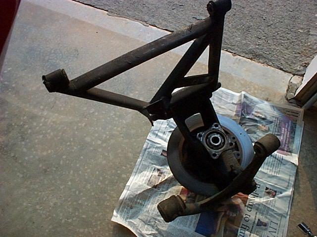
View of the shock and half shaft removed.
Next the lower A arm bolts were removed and the suspension assembly removed. On my car the lower front mount on the frame rail had to be loosened so the A arm mount bolt could clear part of the frame. My car has a extra factory part welded on the frame tube that blocks the path of the bolt. Only the early and mid 1971 cars have this double tube part added.


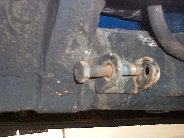
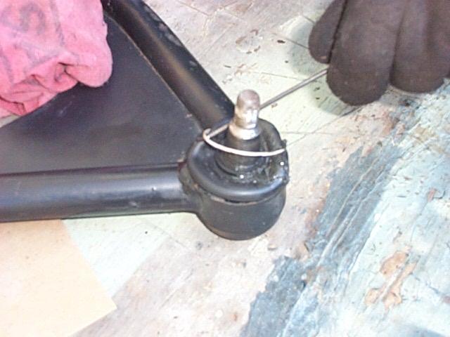
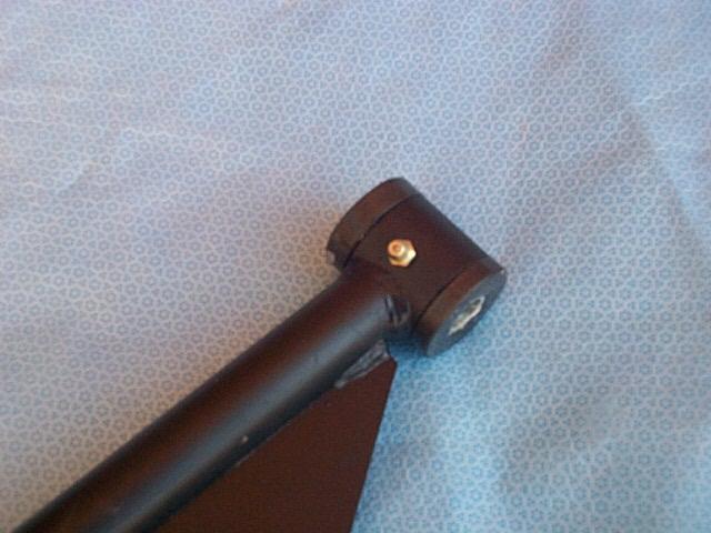
The shaft is removed from the lower A arm and up-right. The cups have O rings to seal the shaft and and keep the grease sealed inside.
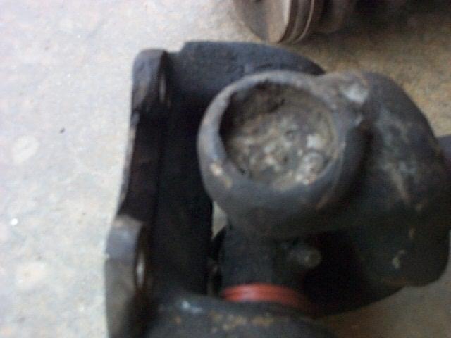
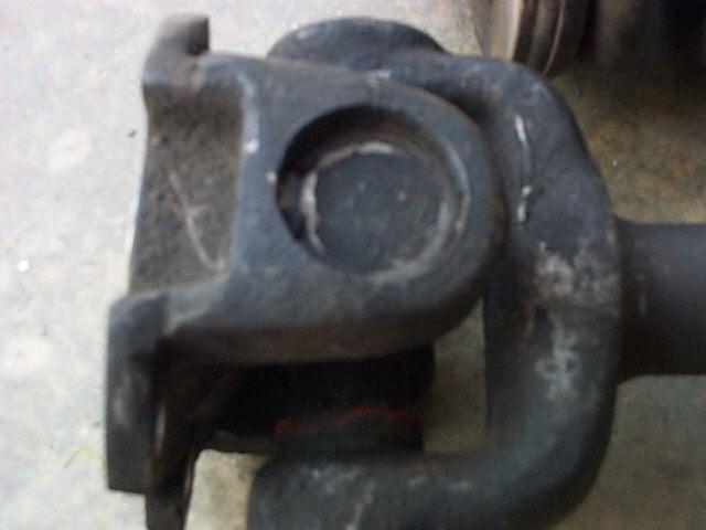
The image the left shows how some nut welded the U joint cap. The image on the right shows that the cap on this U joint has been spinning in the yoke. Other than the half shafts all of the other parts look good.
October 24, 2000 - Clean Up
Last night, I spent some time cleaning the area around the the A arm mounts on the right side of the car. I placed a oil drip pan under the frame area and then used 409 and a scrub brush to scrub away at the dirt. I had cleaned the wheel wells when I fist got the car but was not able to clean behind the suspension areas. After scrubbing with 409 I used a spray bottle with water to wash away the dirt. I wiped the areas with paper towels and re-scrubbed the area until it was clean. What a mess but the drip pan helped! Latex gloves are also helpful when working with dirty and greasy parts. It sounds weird, but give it a try. You can buy them at auto parts stores. All of the areas have undercoat that is in good condition so I plan to use some flat black spray paint to cover the clean areas and make them black again. In the image below you can see that the undercoat still has a slight Oklahoma dirt color but it is pretty clean.
Today I removed the left suspension. Soaking the nuts and bolts with penetrating oil really helps to get the suspension parts loose. Had to loosen the lower front A arm mount at the frame rail for the A arm bolt to clear the double vertical frame tubes on my car.
The boot on the left ball joint has a small hole but the ball joint feels good and has no play. It looks like I will need a new boot for the ball joint. The axle on this side has a slight amount of play and I hope it is in the bearing not a bad axle.
The D axle was on the right side (passenger side) and the S axle was on the left (driver side) and both axle nuts are tight. The axles are stamped on the inside edge with the D and S to indicate the side of the car. The idea of the two different axles is to keep the axle nuts tighting as you drive. The tight axle nuts are good news and I hope the axles will be OK.
The left side went a little easer than the right side as I'm getting better at the process. I did not need to loosen the exhaust on this side to get the half shaft out. The half shaft was removed before the suspension was removed.
The ETA for axle sleeve and spacer has been moved out to next week so I'll have some time to clean up the up-rights and A arms before the bearings parts are ready.
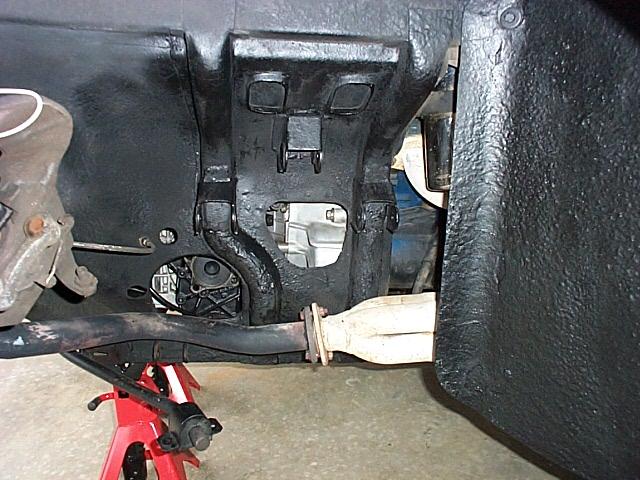
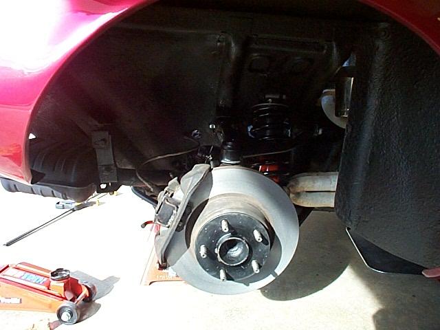
View of the wheel well after the final cleaning.
November 4, 2000 - Taking The Axles Out
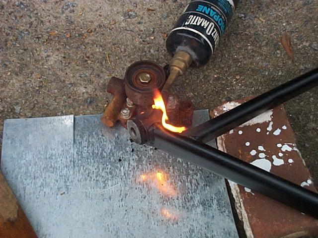
The next phase is taking the uprights apart and removing the bushings from the A arms. The mechanic likes to burn the rubber out of the bushings. The mechanic setup the torch as the first order of business to burn the bushing rubber while we worked on the uprights. It is important not to heat the A arms very hot, you want it just warm enough for the rubber to burn.
I left the upper A arms on the uprights . The mechanic uses a air hammer with a flat tool to shock the top of the upright and the ball joint tapered stud came right out. The upright has a projection that is designed for the hitting or shocking to release the ball joint. Both ball joints were in good shape.
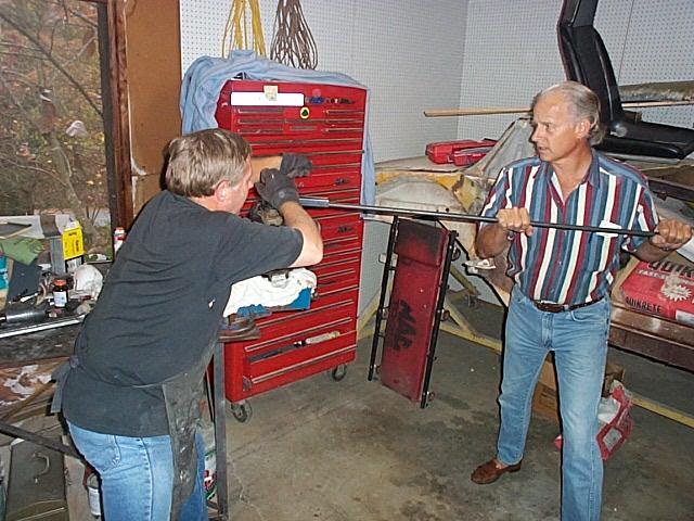
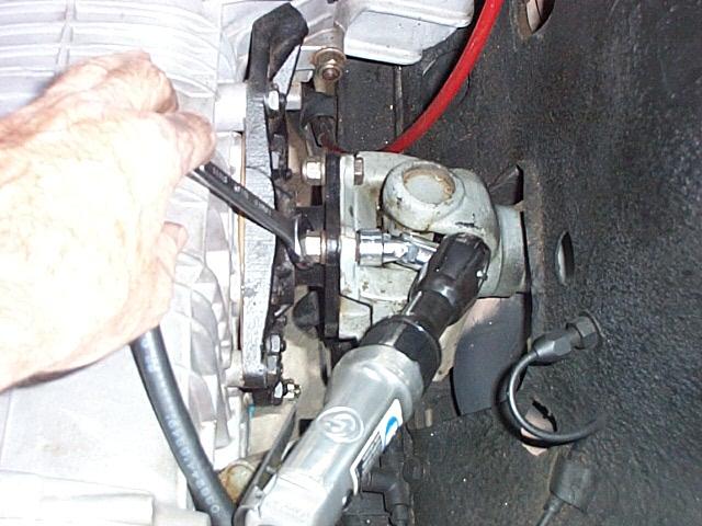
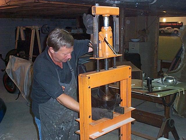
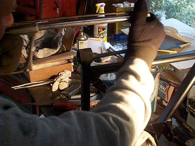
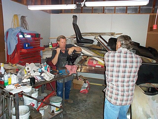
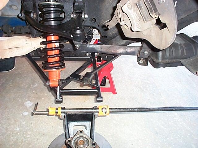
The mechanic on the left and Dick Koch on the right use a torque multiplier tool to release the axle nut. The torque multiplier tool is a geared device that connects between the axle nut socket and the wrench that increases the torque. It makes applying hundreds of pounds of torque easy.

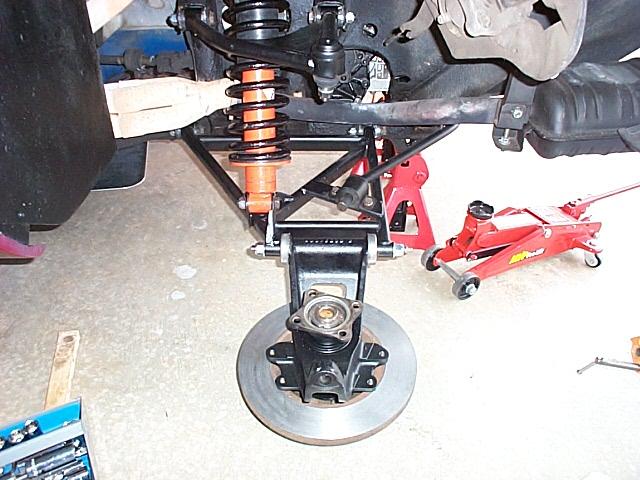
The upright with the axle nut and yoke removed.

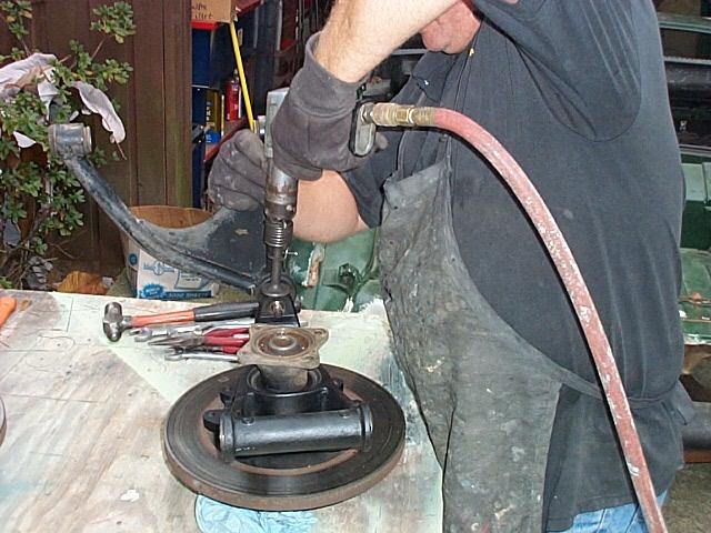
The mechanic's press did not have a way of griping the upright so he drove the axles out using a soft tool inserted into the end of the axle and the a very heavy lead hammer. The mechanic has used this method before and it seemed to work well. He will be welding up a tool for his press to so that the press can be used in the future. The axles were very tight in the upright bearings.
The way the axel should be removed is to support the face of the brake rotor on a short piece of iron sewer pipe that is just large enough to fit around the hat part of the rotor. Place the assembly in a hydraulic press and press out the axel. The rotor MUST be carefully supported all the way around the face or it will crack and break. As pressure is exerted on the axel the wheel studs will slowly be pulled out of the axle flange until the hat portion of the brake rotor comes in contact with the face of the upright. At this point as more pressure is added the axel will start moving down and out of the bearings and out of the upright leaving the bearings inside the upright.
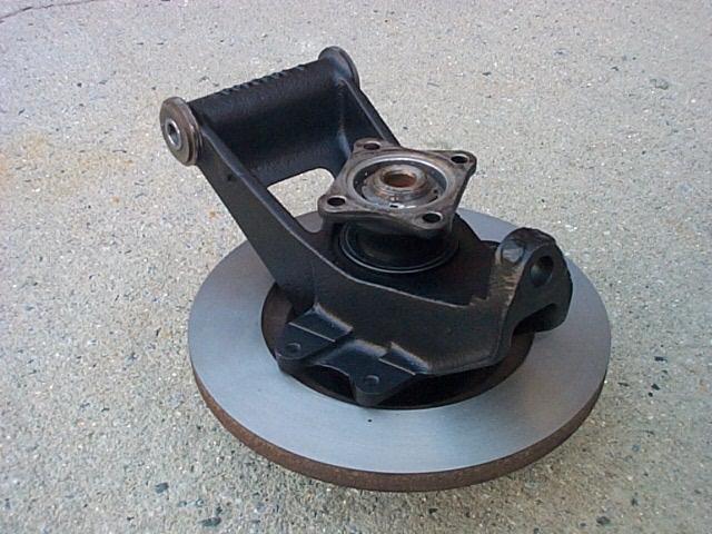
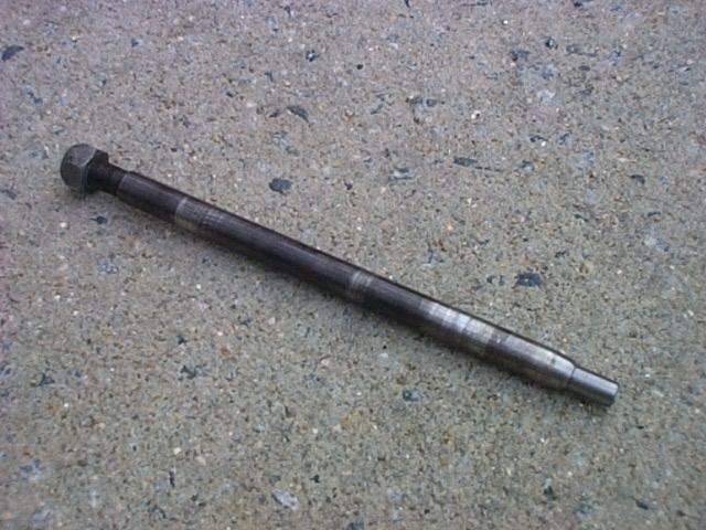
View of the axle removed from the upright.
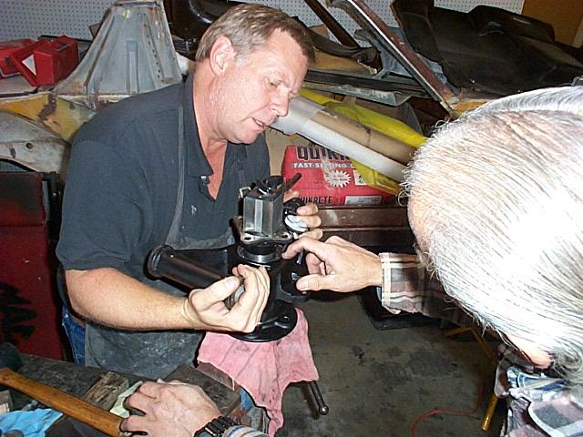
The mechanic used a screw driver tool that rotates when hit on the top to start turning the bearing retainer ring screws. Other than the press fit, this little ring is the only thing that keeps the axle and bearing assembly from sliding out of the upright.
The mechanic used the press to remove the bearings from the upright. While the mechanic and Dick worked on this I took the rotors to a brake shop and had them turned. As the rotors can not be removed from the car without taking the axles out this is a good time to make sure that they are true.
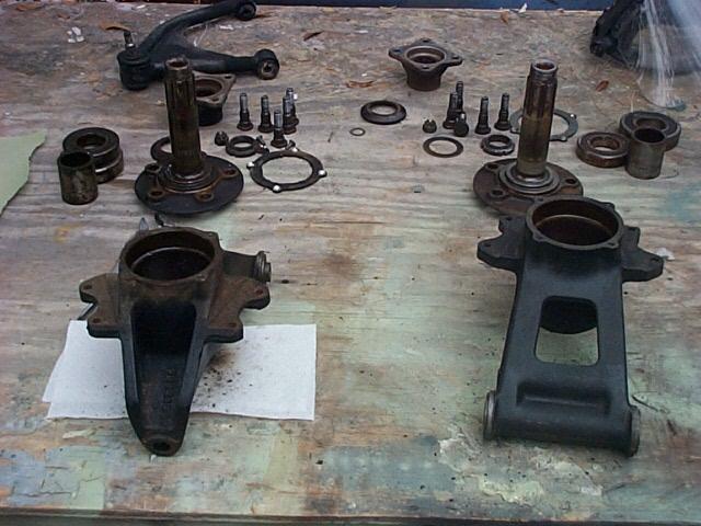
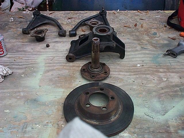
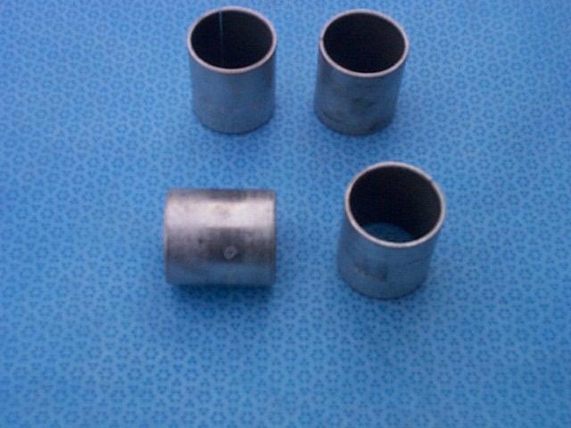
View of both uprights with the axles and bearings removed. In this image you can see the face of the upright where the bearing retainer ring was attached with screws and the rings in the background. In the image you can see the larger outside barring and smaller inside barring and the spacer that fits between them. The outer barring is a press fit into the area you can see on the face of the upright and is only held in place by the retaining ring and screws. The inside bearing is also a press fit but its position is controlled by the spacer that goes between the two bearings. Because the inside bearing is bound to the outside bearing with the spacer you can see that all of the side loads exerted on the car are carried by only by the outside bearing race.
The axle on the driver's side of the car that had a very small amount play in the wheel but was in good shape. The axle on the passenger side that had no play in the wheel and the rotor started rubbing on the upright had about a .005 deep fretted area under the outside bearing. All of the bearings looked like water had infiltrated the upright and had gotten on inside of the bearing case and the spacer between the bearings. Rust was evident on the spacers and some spots on the outside of the bearing cases. It all looked pretty messy as you can see in the above image.
The integral seals on the stock bearings are not very good at keeping water out of the bearing and upright. I expect the water played a big roll in damaging the bearings. The upright on the driver's side is a newer style upright that has two shock bumps molded at the top by the ball joint, but was also the upright that had the bad lower shaft. It is interesting that the wheel that had no play was the one with the bad axle. Apparently the fretting of the axle took place sometime ago and some one just tightened the axle nut without taking the assembly apart to find out what was wrong. Tightening the axle nut eliminated the looseness that must have been in the wheel but did not fix the problem. I think this proves that checking for looseness in the stock bearing assembly is not a definitive test. The other wheel that had play was just a looseness in the bearings.
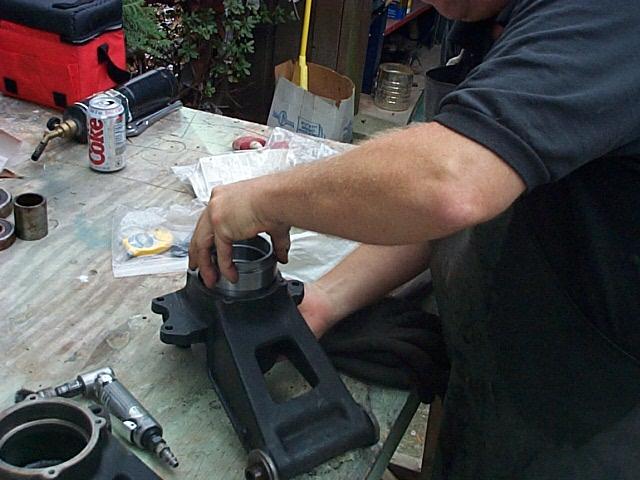
The mechanic cleaned the inside of the upright with a wire wheel on his air tool to make it super clean. The insert and upright insides were cleaned with acetone and the bearing sleeve was installed in the upright.

The original bearing retaining ring is installed and the screws cleaned and torque down using Locktight.
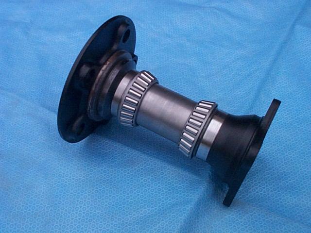
View of the axle, bearings and yoke as an assembly.
View of the outer side of upright with the sleeve installed.
View of the inner side of upright with the sleeve installed. Unlike the original ball barring setup where the side loads on the car were carried only by the outside bearings on this new setup it will be carried by both bearings.
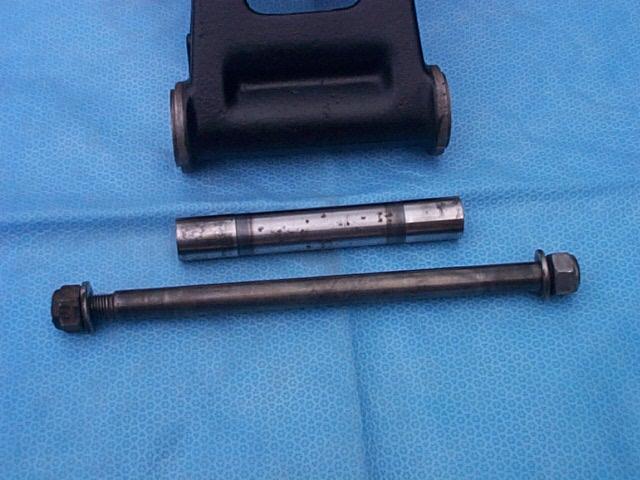
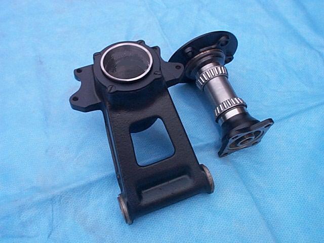
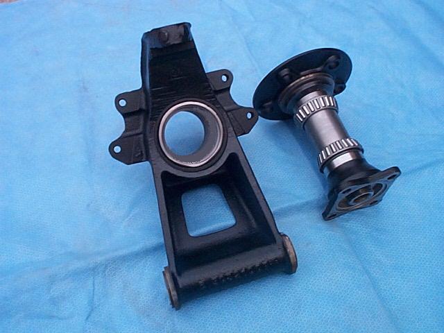
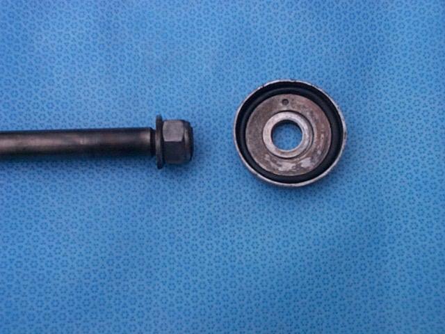
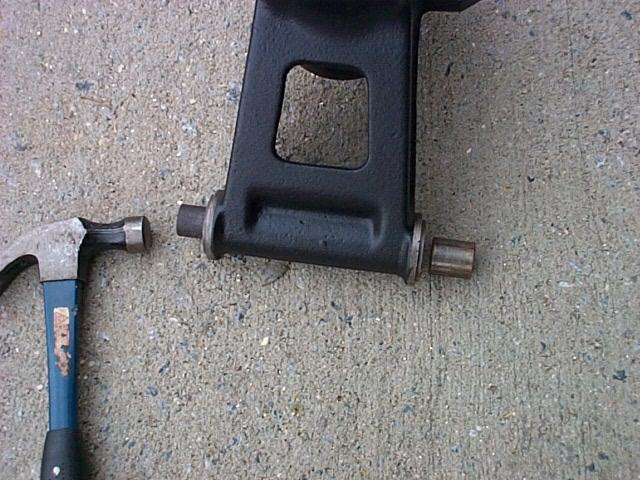
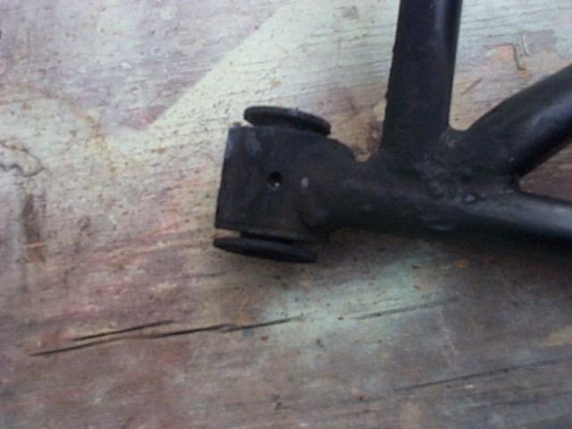
View of the upright lower shafts. The short shaft rotates on bushings inside the upright and the longer shaft goes through the A arm and the short shaft to hold the assembly together. The lower part of the upright had no looseness when on the car but needed rebuilding.
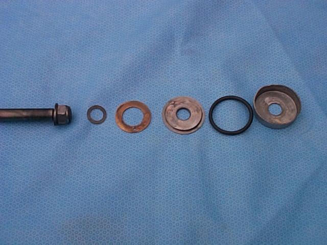
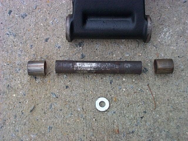
The is the exploded view of the thrust assembly that fits between the A arm and the upright. Note the rubber O ring to seal the assembly. The O ring should be shown one position to the left in the image for the proper assembly order. The washer with the brass color needs to be replaced.
Assembled view of the thrust assembly.
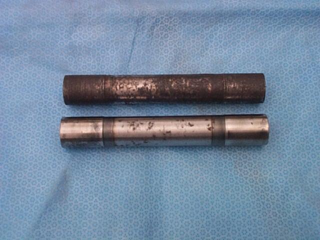
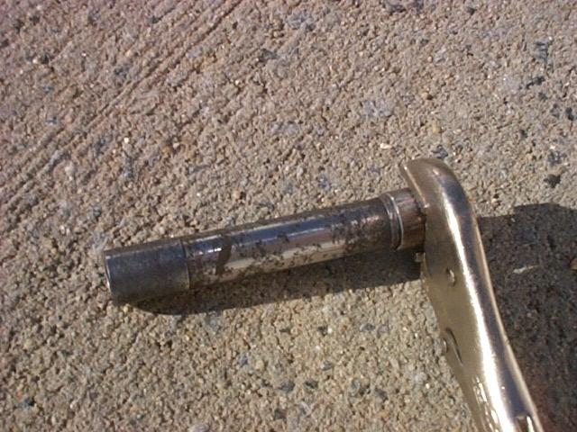
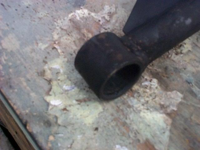
View of upright eroded shaft on the top is from the left side of the car and the good shaft on the right side. The upright bushings on the left side were eroded and had frozen on the shaft. The shaft had to be driven out.
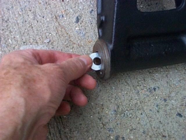
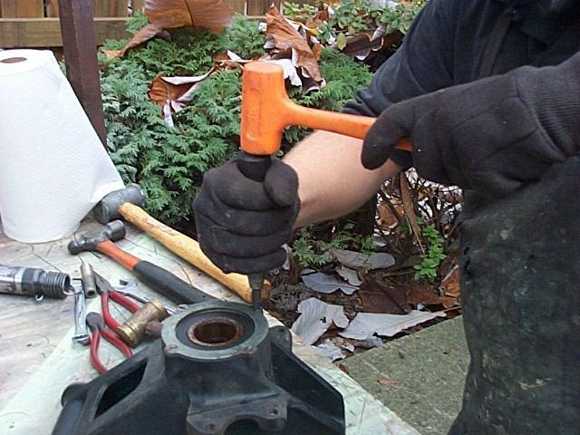
To remove the upright bushings a thick 1" washer was filed on both sides so that it would slide in the upright horizontally. After the washer was moved past the inside edge of the bushing it was flipped vertical and moved to the back edge of the bushing.
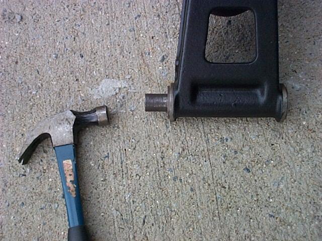
The old damaged upright shaft was placed in the upright and against the washer face and a hammer was used to drive the bushing out.
View of the first bushing removed.
View of the both bushings removed, the bad shaft and the removal tool.
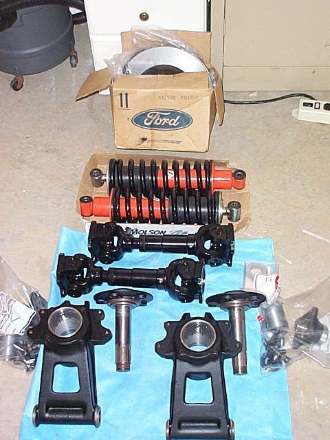

View of the parts ready for assembly and the Pantera awaiting the parts. We had hoped that we could complete all of the work on Saturday but as this axle system is the first production set of parts it's taking a little longer to fit everything and make sure that is right. I will also need to get on the phone Monday to Pantera Performance and order new lower upright shafts and some bushings. Looks like my Pantera is going to miss the first "Atlanta Donut Derelicts" meet next Saturday.
November 6, 2000 - More Parts
Today I called Pantera Performance and ordered their greaseable lower upright shaft assemblies for slightly more money than just the cost of the stock shaft or sleeve that was damaged. Decided that I would replace the upright bushings in both uprights to work with the two new shaft assemblies. I also decided to replace the upright end thrust washers that mate with the ends of the upright.
November 8, 2000 - Parts Arrive
The new parts arrived from Pantera Performance.
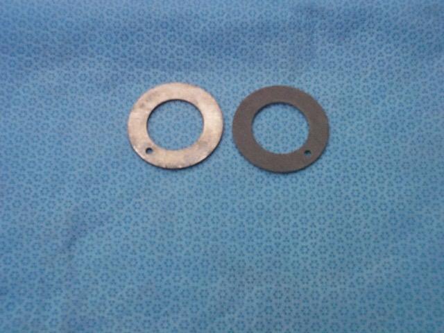
View of the two different sides of the upright thrust washers. View of the left washer has the side up that mates with the end of the upright up. View of the right washer has the side up that mates with the other thrust washer in the cap. The dark color is a Teflon coating. The washers that I removed from the car had a brass color and were in bad shape. If you can see brass they need to be replaced.
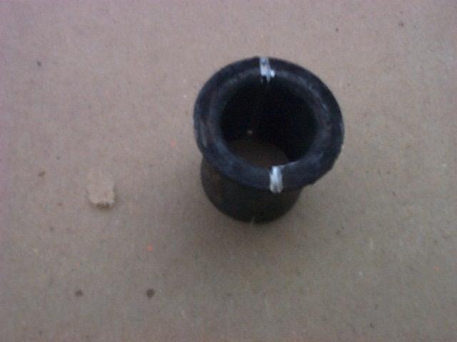
View of the new upright bushings. They are also coated on the inside with Teflon and have a dark color. The bushings that I removed from the car had a brass color and were in bad shape.
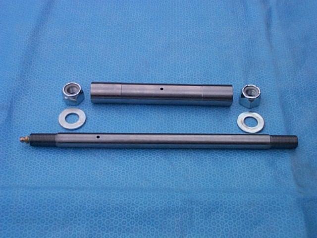
View of the cool upright lower shaft kit. The shaft has a grease fitting on the left end. It's hard to see in the image but the shaft has a small flat area that extends to the right of the hole to feed grease to the outside of the sleeve shown above the shaft and on to the bushings.
I spent some time on the phone with Dennis at Pantera Performance to discuss the best way to install the bushings and assemble the upright to the lower A arm. What a great group of people to work with.
November 9, 2000 – Installing The Upright Bushings
I didn’t have a bushing installer so I used one of the old upright sleeves with one of the old upright bushings clamped to the very end of it with some vice grips. Before clamping the bushing to the sleeve I filed the end of the bushing that would contact the new bushing so that it had a nice flat contact area to push the new bushing into the upright. The old bushing was positioned and clamped on the sleeve so that a small area of the original sleeve bearing surface would slide inside of the new bushing but the remaining part of the new bushing would have the smaller diameter of the sleeve going through it. Make sure that the old sleeve is clean and polished so that it does not cause problems with the Teflon coating that is inside of the new bushings.
I cleaned the area where the upright bushing would be installed in the upright and wiped the area with WD40. I place the end of the new bushing in the upright opening, sprayed it with WD40 and then inserted the homemade bushing tool into the upright. The tool is moved down so the flat area of the old bushing contacts the edge of the new bushing. I supported the other side of the upright with a wood block, held a wood block at the end of the tool and hammered the new bushing into the upright so it projected about 1/32" above the side surface of the upright. I then used a 13/16" socket placed on the exposed end of the bushing to seat the bushing so that it was flush with the end of the upright. I then installed the bushing on the other side of the upright, being careful that the end of the tool did not contact the new bushing on the other side of the upright.
When the bushing is installed it may not seat completely evenly around the inside of the upright because the bushing is split rather than a full bushing ring. This may cause the new sleeve to fit too tightly in the two bushings. I used the old sleeve and inserted one end into the bushing and then worked the sleeve up and down and side to side to force the bushing to move out against the seating area in the upright. After some work the new sleeve would slide snugly but smoothly into the upright and could be moved in and out with very strong finger pressure.
I decided after some more examination of the end cap thrust assemblies that I should replace the small center washers and O rings. The small center hardened washers control how tight the thrust washers will be compressed and lock the upright sleeve to the A arm so that the upright will rotate on the sleeve and upright bushings.. Some of them showed some fretting and seemed to be too thin and looked like they would cause the assembly to bind or would let the upright sleeve turn on the lower upright shaft. Another call to Pantera Performance took care of the washers and O rings. I tried NAMPA auto but could not find an O ring that was the correct size. It must fit correctly to seal the cap and the end of the upright.
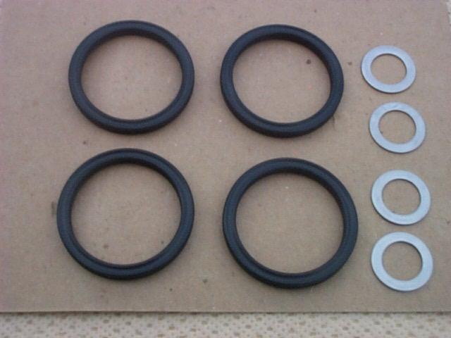
View of the Pantera Performance O rings and center hardened washers. The Pantera Performance O rings are square to fit the shape of the upright. One washer fits on each end of the upright sleeve. The washers sold by Pantera Performance should provide the correct spacing, assuming that the sleeve is the correct length.
November 10, 2000 - Removing The A Arm Bushings
The mechanic has not made the Fred Terry bushing removal tool yet so the following is the usual way to get the bushings out.
View of the A arm with the rubber bushing melted away.

The the end of the inside sleeve is knocked of with an air chisel.
View of the A arm and bushing.
The mechanic cuts the side of the bushing with two cuts on each side of the bushing. This is tricky because you want to cut the bushing but not the A arm. After the cuts are made he heats the bushing from the inside so it will expand and then shrink. The A arm is not heated only the bushing. He lets it cool, sprays it with penetrating oil, puts it in a protected vice, and taps the bushing out with a hammer and punch. Some of the bushings almost fell out.
View of the sleeve removed.
November 10, 2000 - Replacing The Ball Joint Boots
Both of the ball joints were in good shape but each had a small hole in the rubber boot. He has a hook shaped tool that he uses to hook onto the retaining ring and remove it.
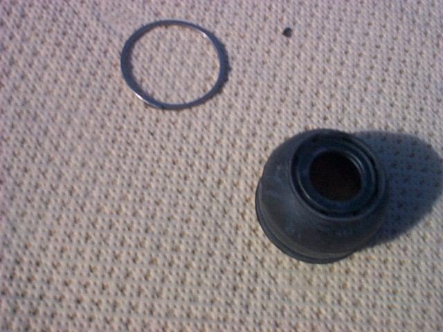
View of the new ball joint boot. The area around the ball joint was cleaned of old grease and new grease applied around the ball joint opening.
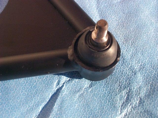
View of the completed boot installation.
November 10, 2000 - Installing A Arm Bushings
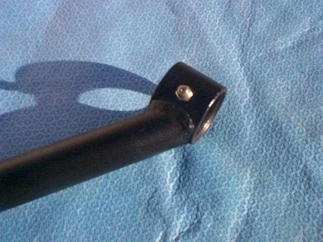
The A arms were drilled and tapped and grease fittings were installed.
The inside of the A arm opening was cleaned, NAPA auto parts anti-seize was applied to the inside of the A arm and the new bushings pressed in place
November 11, 2000 - Installing The bearings
The bearing assembly was installed in the upright and the mechanic and Dick used the torque multiplier tool to tighten the assembly to check the preload. I can not imagine how this could be done correctly without the torque multiplier. The preload adjustment is a test to check how tight the bearings are in the assembly. Because this axle setup is an assembly this process normally would be done before the sleeves are installed so a complete bearing kit could be available with the adjustments pre-done. As this is the first set to be installed we installed the sleeve in the upright first.
A dial indicator is used to check the pre-load. The axle on this system is a sung slip fit in the bearing cones so the axle can be removed easily without damaging bearings. The axle is hand polished down to create the snug slip fit. Not much polishing is required as the stock axle is a 0 clearance interference fit with the bearing cones.
After the pre-load was checked the axle was removed, the bearings are packed with grease, the inter-sleeve coated with extra grease, seals installed and the assembly torqued. The two seals look like they will do a great job of keeping water out of the complete upright and axle assembly.
November 12, 2000 - Installing The Shocks and Uprights

The anti-roll bar was attached on both sides before the shock was installed. This allows the lower A arms to be moved down so the the anti-roll bar mountings bolt to the A arm without any pressure. My car had poly bushings on the anti-roll bar rathen than the original rubber bushings. The anti-roll bar and bushings were cleaned and then lubed with NAPA auto parts anti-seize before the bar was installed.
View of the driver side of the car. The upright is positioned in on the floor before the thrust washer assemblies are installed on each end. Be very careful that the hole in the thrust washer next to the upright indexes on the small projection on the upright. I put grease between each of the washers and lightly greased the O rings. The grease helps hold the assembly to together. Make sure that the outer edges of the cups do not drag or touch the upright.
One of the old lower shafts was ground to a taper on one end to use as a tool to align the upright after it was positioned on the A arm.
After the end cap assemblies were installed on the upright a screw type clamp was used to compress the O rings. I takes a lot of clamping pressure to compress the assembly and then it is a very tight fit in the A arm. I started the upright into the upright by hand making sure that the end cups were aligned correctly. I then placed a block of wood on the end of the upright and tapped the upright part way into the A arm. I found that it worked best if the upright was tapped in so that a floor jack could be placed under the upright and then jacked up from the bottom into the A arm to position the holes. I found it imposable to move the upright by hand to align the holes. After tapping and jacking on the upright the holes looked aligned. I tapped the tapered alignment tool in to each end of the A arm to lineup the holes. The new lower shaft tapped in very easily.
View of the upright with the lower shaft installed. When installed correctly the upright should swing smoothly, but feel snug.

I used a old towel to protect the half shaft during installation.
Next the upright is moved up into position and the upper A arm and ball joint attached. This view is from the passenger side of the car. The half shaft was connected to the axle.
View of the installation completed with the caliper installed.
November 19, 2000 - Summary
I've had a few days to do some test driving with the Pantera and the suspension rebuild is working great. The car feels much tighter on the road and overall there is a super improvement. The back end is lower with the spring spacers removed from the back shocks.
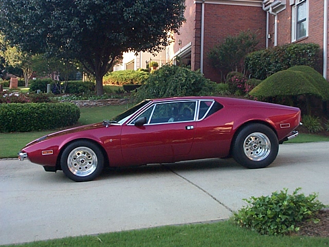
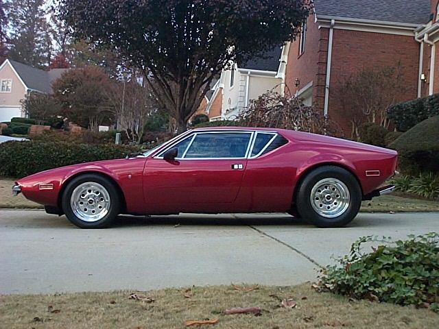
The image on the left shows the stance with just the front shims removed. The image on the right shows the stance with the front and back shims removed.
June 1, 2001 - Follow-up
In January I upgraded to Pantera East wheels and new fat Dunlop Z rated tires. With the front and back suspension completely rebuilt and the new wheels and tires the car handles outstanding and drives like it is on rails. It was well worth all of the effort!.