The Pantera Place
"Your de Tomaso
Connection"
Replacing
A-Arm Bushings -
Using
A Portable Press
By
Bill Taylor
|
All
of the technical information and product information posted on this
website is offered as general information and is not recommended,
endorsed, guaranteed or presented as professional technical
information. It is recommended that you seek professional help
for the repair or maintenance of your car. Improper
self-maintenance or repair of your car can result in serious injury
and or death. Use of this information is done at your own risk.
|
The
following is a description of a method for removing and installing OEM style
suspension bushings in Pantera a-arms. This method uses a 3/8 inch electric
drill, three hole saws, three pressing adapters, and a purpose built portable
hydraulic press.
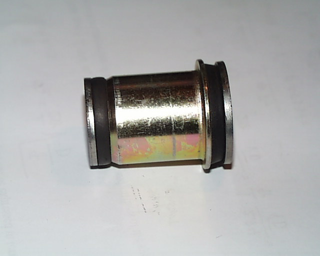
Figure 1 shows an OEM style suspension bushing. The bushing consists of a
central metal tube bonded to rubber. The rubber is bonded, in turn, to an
outer metal sleeve which has a flange at one end. The central metal tube is
swaged to washers at each end.
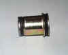
Figure 1
Figure
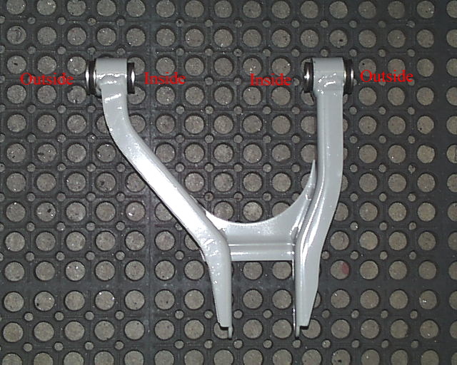
2 shows bushings installed in a Pantera a-arm. The bushings are a slight
interference fit in the a-arm. When the a-arm is installed in the suspension
mounting brackets in the chassis, the a-arm mounting bolt clamps the washers
at the ends of the bushing in the mounting bracket and the bushing does not
rotate on the mounting bolt. The movement of the suspension a-arm twists the
rubber which is bonded between the central metal tube and the outer metal
sleeve. Because the rubber is twisted when the a-arm moves, the a-arm should
be installed in the chassis mounting brackets at the normal ride height
position before the a-arm mounting bolts are tightened. This will prevent over
stressing the bushing rubber when the suspension moves.
Figure 2 also shows labels to establish the location of the a-arm “inside”
and “outside” with respect to bushing mounting surfaces.
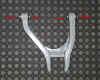
Figure 2
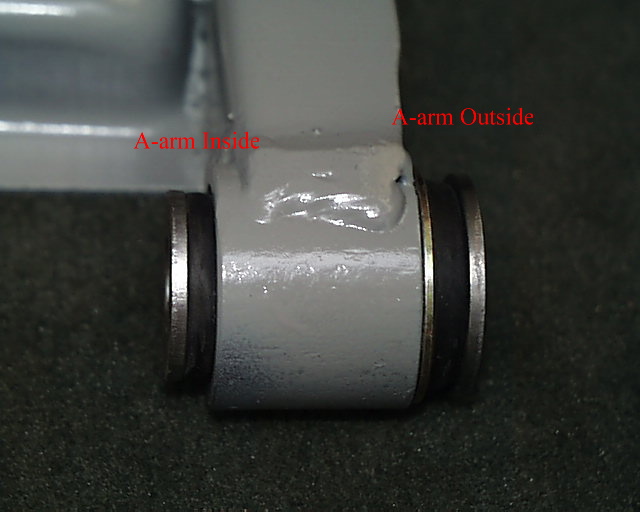
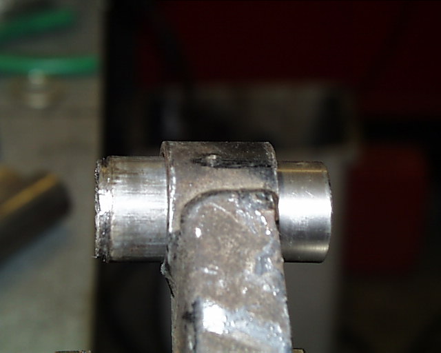
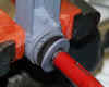
Figure 3 shows the details of an installed a-arm bushing. Note that the
installed bushing extends farther on the “outside” (to the right in the
picture) of the a-arm than it does to the “inside” (to the left in the
picture). The bushings must be installed in this orientation or the a-arms
will not fit the suspension mounting brackets on the chassis.
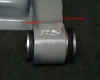
Figure 3
To
remove the bushing from the a-arm, the right hand most washer in Figure 3 must
be separated from the central metal tube, the flange on the bushing outer
sleeve (the metal part adjacent to the a-arm) must be removed, and the rubber
bonded between the central metal tube and the outer metal sleeve must be
removed. The outer metal sleeve can then be pressed out of the a-arm.
Figure 4 shows the three hole saws used to remove all but the outer
sleeve of the bushing. The pilot shaft for each ole saw is sized to fit the
central tube of bushing. No lubrication of the pilot shaft is required.
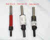
Figure 4
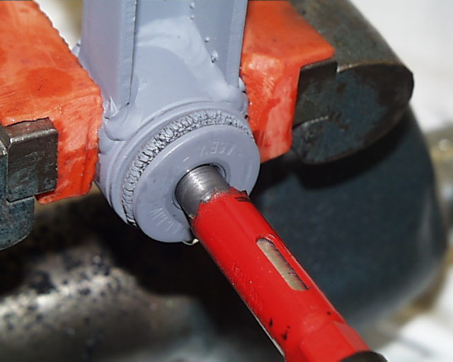
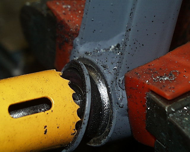
Figure 5 shows an a-arm mounted in a vise and Hole Saw #1 in position to saw
the outside metal washer where it is swaged to the central metal tube. Hole
Saw #1 is a 5/8 inch (16mm) saw with a custom pilot that fits the central
metal tube.
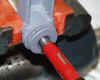
Figure 5
Figure
6 shows the outside metal washer separated from the central metal tube.
Figure
6
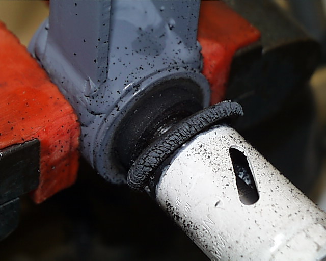
Figure
7 shows Hole Saw #2 in position with a sawn off a small rubber donut and ready
to saw off the metal flange which is part of the bushing outer sleeve. Hole
saw #2 is a 1 ¼ inch (32mm) saw
with a custom pilot which fits the central metal tube. The flange must be sawn
off to gain a surface for pressing the bushing out of the a-arm.
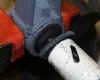
Figure 7
Figure
8 shows Hole Saw #2 having sawn off the metal flange of the outer sleeve. The
#2 hole saws in the two picture are the same size but are of different colors.

Figure 8
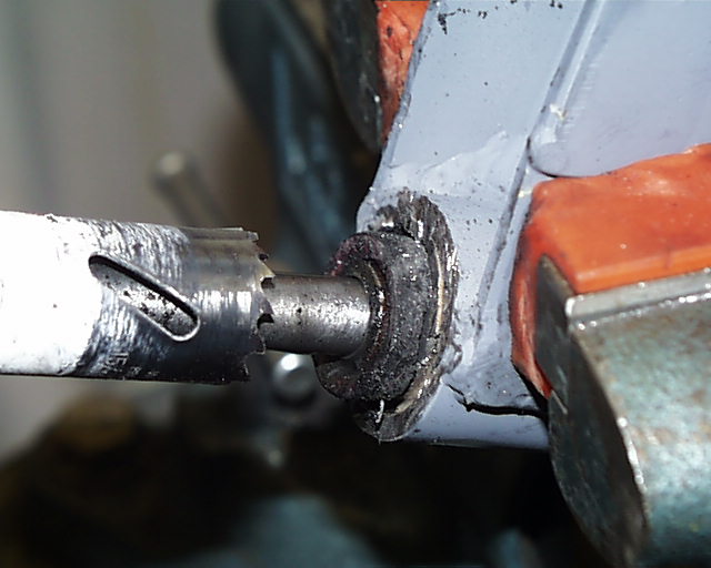
Figure
9 shows Hole Saw #3 in position to cut away the rubber bonded between the
central metal tube and the outer metal sleeve. Hole Saw #3 is a 15/16 inch
(24mm) saw with a custom pilot which fits the central metal tube.
Figure
9
When
using Hole Saws #1, #2, and #3 it will be best to use the same saw on all the
bushings to be replaced before changing to the next saw. This will minimize
the number of times you will need to install and remove the hole saws in the
drill motor.
After using the three hole saws, the outer sleeve will be the only part of the
old bushing which remains in the a-arm. The saws are only used from the
“outside” of the a-arm. The inside surface of the bushing outer sleeve
will be unblemished, flat, and normal to the bushing centerline. This surface
will be used for pressing the outer sleeve from the a-arm.
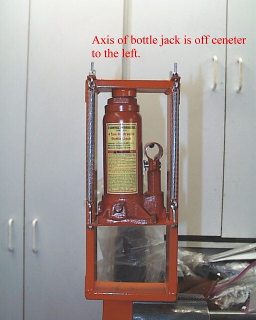
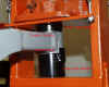
Figure
10 shows the portable hydraulic press. The frame is made of ½ inch by 2 inch
steel welded and all joints reinforced. A 4 ton hydraulic bottle jack provides
the pressing force. So as to keep the press as compact as possible, the
vertical axis of the bottle jack is mounted slightly to the left of center in
the press.
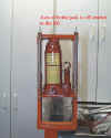
Figure 10
Figure
11 shows the portable press mounted in a vise. The press is mounted offset to
the left to afford easy access for a-arms, bushings, and bushing adapters.
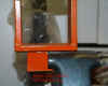
Figure
11
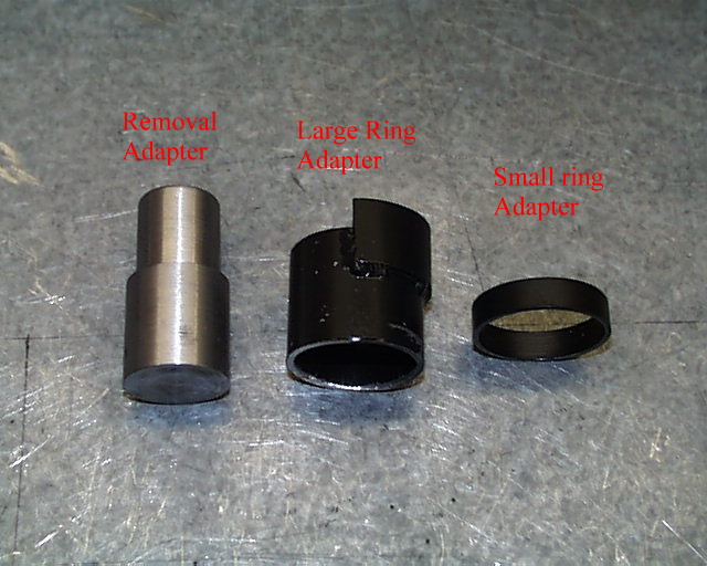
Figure 12 shows the three press adapters used in pressing out old
bushings and pressing in new bushings.
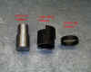
Figure 12
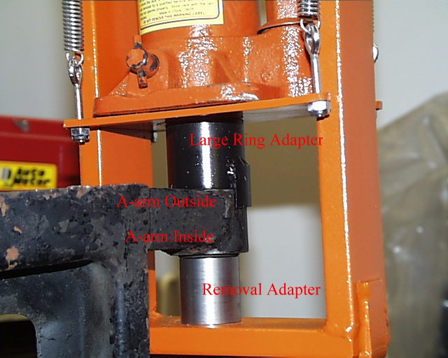
Figure 13 shows an a-arm mounted in the press ready to press out an old
bushing. The Removal Adapter on
the bottom is piloted in the outer sleeve of the old bushing and the Large
Ring Adapter on the top is piloted on the surface of the a-arm. The adapter on
the bottom is solid and is slightly smaller in diameter than the hole in the
a-arm and is slightly longer than bushing. This allows the Removal Adapter on
the bottom to fully press the outer sleeve of a bushing out of the a-arm. The
Large Ring Adapter on the top is hollow and allows the bushing to be pushed
clear of the a-arm.
When pressing the bushings, position the a-arm and adapters under the
center of the hydraulic bottle jack.

Figure 13
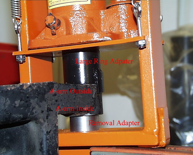
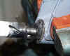
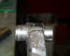
Figure
14 shows the old bushing outer sleeve pressed half way out.
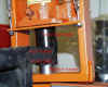
Figure 14
Figure
15 shows an a-arm with an old bushing outer sleeve pressed half way out.
Figure
15
After fully pressing the old bushing outer sleeve out of the a-arm, the a-arm
opening should be lightly sanded with fine sandpaper, checked to be free of
burrs, cleaned, and lightly coated with oil. The new bushing is a slight
interference fit in the a-arm. If the bushing can not be fully seated because
of rust, dirt, burrs, etc there is no way to remove the bushing without
destroying it.
NOTE: Even with a 4 ton press, you may find a bushing which will not
move. If this happens, insert a hacksaw thru the center of the outer bushing
sleeve and cut a groove completely thru the outer bushing sleeve. Do
not cut into the a-arm. This groove will release the interference
fit pressure on the bushing and the bushing may now be pressed out.
After
fully pressing the bushing out, a new bushing can be pressed in. The new
bushing must be pressed in using the flange which is part of the outer sleeve.
The outer sleeve flange must be used for pressing the bushing in to protect
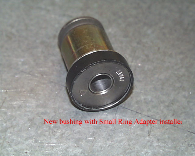
the rubber bonding. Figure 16 shows the relationship between an OEM style
bushing and the Small Ring Adapter used to press the bushing into the a-arm.
The Small Ring Adapter bears on the outer sleeve flange but prevents the
pressing force from bearing on the outer washer or central metal tube.
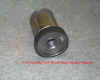
Figure 16
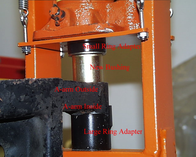
Figure
17 shows a new OEM bushing and the adapters used to press the bushing into the
a-arm. The Small Ring Adapter at the top is mounted on a new bushing and
applies the pressing force to the flange of the new bushing outer sleeve. The
Large Ring Adapter on the bottom supports the a-arm and provides space for the
inside end of the bushing to clear the a-arm. The bushing is fully seated when
the outer sleeve flange if tight against the a-arm.
Bushings must be installed with the bushing flange on the “outside” of the
a-arm. The front bushing is pressed in from the front most side
(“outside”) of the a-arm and the aft bushing is pressed in from the aft
most side (“outside”) of the a-arm. If the bushings are installed with the
bushing flange on the center part of the a-arm or with one bushing flange on
the outside of the a-arm and the other bushing flange toward the center of the
a-arm, the a-arm will not fit the mounting flanges on the chassis. When the
bushings have been installed, they cannot be removed without destroying them.
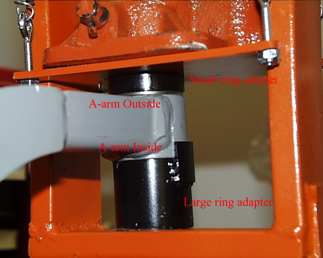
When using the portable press, the orientation of the a-arm, whether pressing
old bushings out or new bushings in, is always with the inner edge of the
a-arm bushing opening toward the bottom of portable press. Old bushings are
pressed out in the upward direction and new bushings are pressed in the
downward direction.

Figure
17
Bushings
require considerable force to press out and in. An OEM bushing which has never
been replaced has not moved in over 30 years and has grown very fond of the
intimate relationship it enjoys with the a-arm.
Figure
18 shows a new bushing fully seated in the a-arm.
Figure
18
Figure
19 shows the details of the adapters used to press the bushings in and out.
The adapters are made from 1
1/2 inch bar
stock and 1.5 in OD 0.090 wall
thickness tubing.
The
0.375 deep small spacer has the ID opened to 1.375 inches to fit the OEM
bushing.
The
positioning tab on the deep adapter is made from a section of 1.5 OD tubing
with radius opened as required to fit. This positioning tab is not
absolutely
required, but it makes the pressing setup easier and more secure.
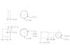
Figure 19