My
Pantera had very slight free-play in the steering column linkage that was
caused by the nylon clips in the steering shaft slip joint wearing.
The play was small compared
to many Panteras I’ve seen but I decided it should be fixed.
It was one of the few areas of the car that I hadn’t inspected
or rebuilt so
I
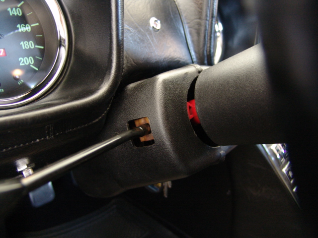
knew that it deserved some attention. While
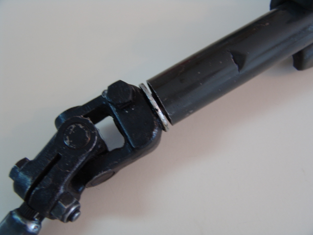
I was looking at the slip joint I also noticed that the U joint at the bottom
of my steering column was rubbing on the bottom of the steering column tube.
Someone had put a large washer between the parts and lubed it up pretty
well so it wasn’t noticeable when tuning the wheel.
My
car has an aftermarket Lecarra steering wheel and after seeing no gap at the
bottom of the steering column tube and the U joint I knew someone had most
likely over tightened the steering
wheel retaining nut and damaged the lower bushing in the column.
The Lecarra wheel does not have a very large tapered area below the
splines and over tightening the nut will pull the wheel down,
coil binding the spring on the top of the steering shaft and will pull up and
or damage the lower bushing.
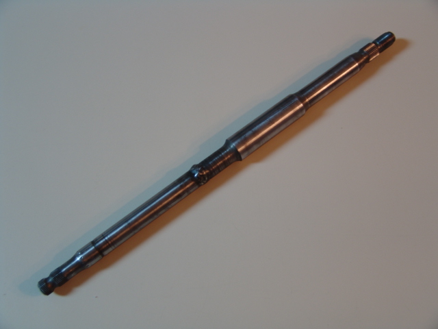
This
article will go through the process of removing and rebuilding the steering
column.
Remember
that anytime you are working on the steering system of any car you are working
on an absolute critical part of the car. Mistakes
could cause the steering system to fail resulting in the loss of control, the
car crashing and serious injury or
death. You should seek a
professional and certified auto mechanic with experience with the Pantera
steering system to do the work for you. If
you are not a professional and certified auto mechanic do not attempt to work
on the steering system of your Pantera.
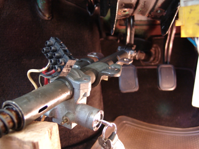
Before
starting the steering column removal, disconnect the battery and center the
steering wheel. The parts are greasy so it’s a good idea to cover your
floor mats. The steering column is
held to the steering column support with four bolts.
My car had Allen head bolts in the back bracket and normal bolts on the
front bracket. The plastic cover
around the turn indicator lever and ignition switch cannot be removed until
the column is dropped down away from the dash. They are held with one screw on
each side and the front parts have large
holes that go above
the back mounting
bracket.
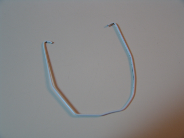
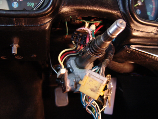
I
made this coat hanger tool to help hold the column up after the mounting bolts
are removed so it is easier to work with the wire terminals without putting a
strain on the wires.
I
dropped the column down enough to get plastic covers off and then held the
column up with the tool to work on disconnecting the terminal strip and
removing the turn indicator assembly. Make
a chart for the wires before you remove them from the block.
The
turn indicator assembly is held on to
the column
tube with a clamp and two screws. I
left the steering wheel on until I removed the column assembly from
the car. Be sure to scribe a mark
on the wheel hub and shaft so you can put in back on in the same position. After
the wires are disconnected the steering assembly can be lowered and detached
at the slip joint. The upper shaft just slides out of the lower shaft. I
scribed the slip joint to make sure I could put it back on the same side.
My Lecarra
wheel does not have a place to install a wheel puller so after
removing the retaining nut I used a block of wood and hammer to drive the
steering shaft out of the wheel
hub.
Be sure to mark the red turn indicator cam so you can put it back in
the same position.
Before
removing the U joint from the shaft I scribed the end of the shaft and the
edge of the U joint so I could put it back in the same spline position.
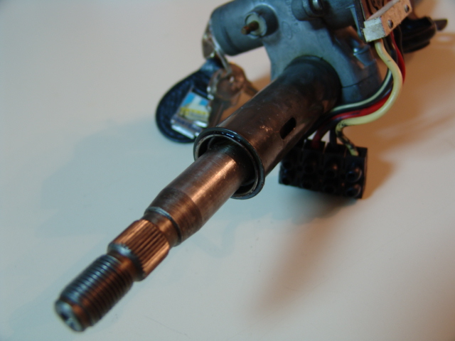
I
was surprised to see that the lower plastic bushing was in good shape but that
the spring steel retaining ring had slipped
out of the groove in the shaft and had moved
down to the bottom of the shaft.
I was even more surprised that someone had gone to a lot of work to
neatly peen the shaft to hold the ring in place at the bottom.
I don’t know why they would do that.
They apparently didn’t understand that the ring belonged in the
groove about 1” further up the shaft and with
a washer rides against the lower
edge of the bushing to hold the shaft in position.
I
used the shaft to tap the upper bushing out and the then used the shaft to
push out the lower bushing out.
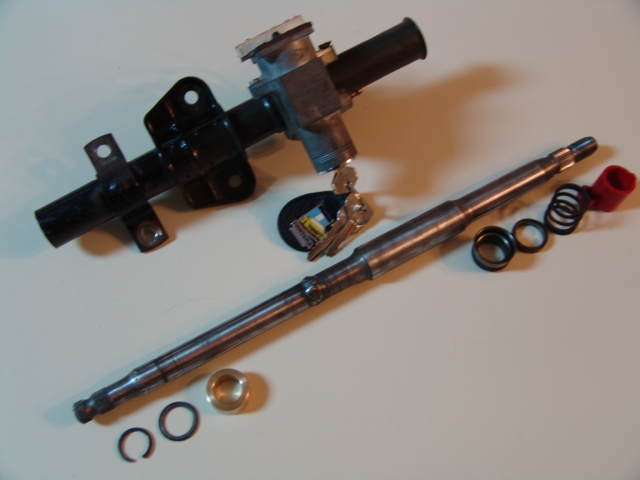
Images
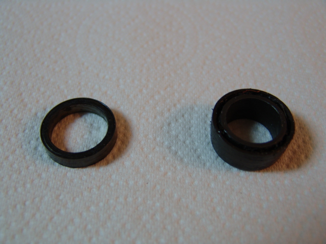
of the column parts. I dressed the
peened mess up at the bottom of the shaft with a file so the new bushing would
slide over the area smoothly.
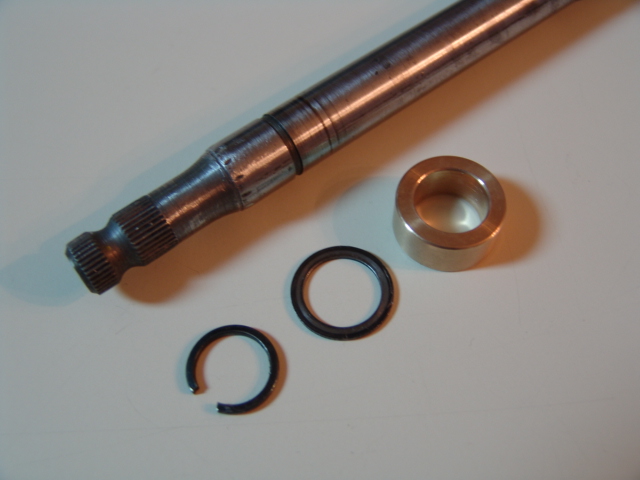
The
old plastic bushing on the right
and spring spacer on the left.
After
cleaning everything I tapped the new bushing (purchase from Pantera
East or Pantera Performance) up the lower end
of the tube until it seated on the tabs in
the tube. I used a large socket that was almost the same size of the inside
diameter of the column tube so the force was on the outer edge of the bushing.
The bushing is a tight fit. I
greased the bushing well after it was in place.
I greased the shaft well and inserted it from the top of the tube and
through the new bushing. Before
putting the washer and retaining ring back on the shaft I reshaped the ring
smaller so it would be a very tight fit in the groove. The lower part of the
shaft is tapered so the retaining ring can be pushed
up the shaft and into the groove.
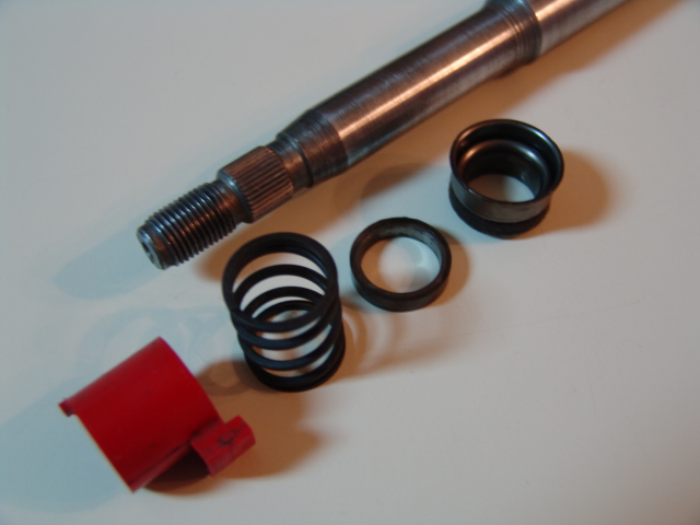
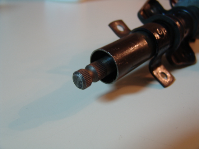
The
next step was greasing the upper bushing and tapping it in place.
View of the assembly.
I
greased the bushing and shaft
well
and slid the spring on. To provide more
space for the spring and prevent coil bind I did not use the upper spacer that
was originally
below the spring.
The U joint was installed on the
lower end of the shaft. I decided
to put the big washer back on just in case I had a problem in the future with
the retain ring.
The steering shaft should turn feely in the bushings.
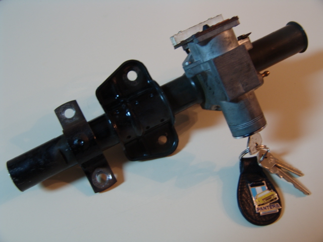
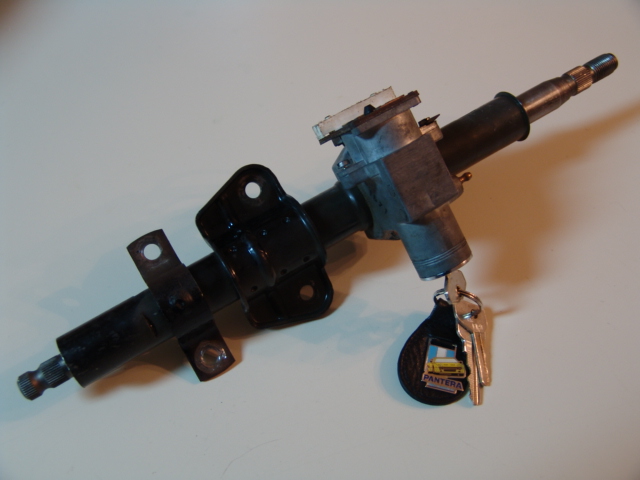
View
of the complete assembly.

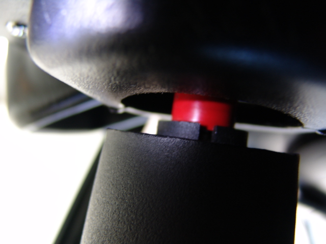
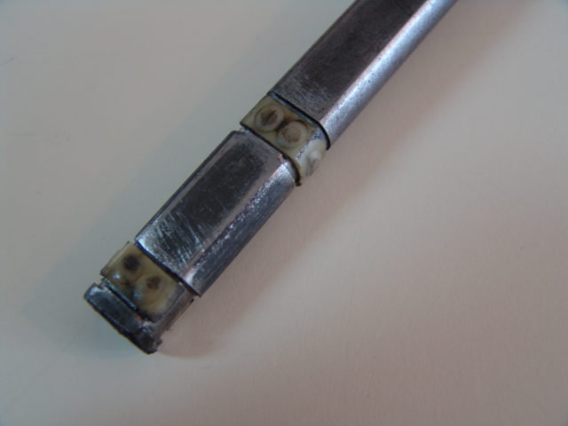
The
tension nubs on the plastic clips
used
in the slip joint were worn down a little and
currently new ones are not available from the vendors or the factory.
I debated about welding the slip joint
as some
vendors recommend
but then others say absolutely
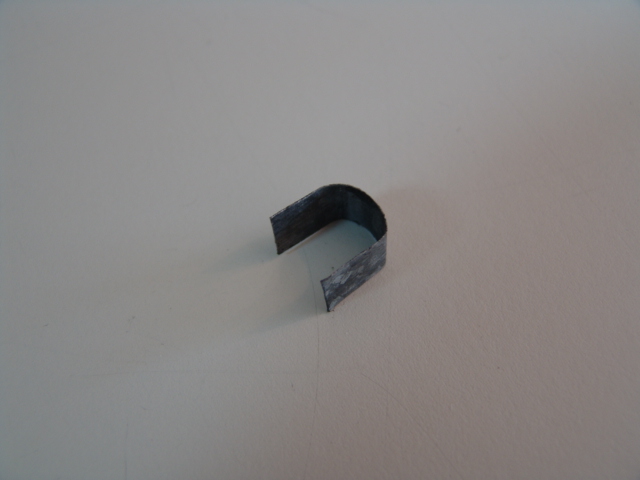
do not weld. I decided to try inserting
steel
shims (made from galvanized steel flashing about .015 thick) under the plastic
clips to compensate for the worn nubs. I
tried a full C shaped shim that wrapped around both sides of the shaft but it
was too thick so I cut one side off making it J shaped and it was perfect.
A
friend
recently used this idea on his car and it took a full C shape to take up
the play.
The shim covers the flat part
of the shaft and wraps around the curved side. The
thickness of the shim needed
is dependent on how badly the nubs are worn.
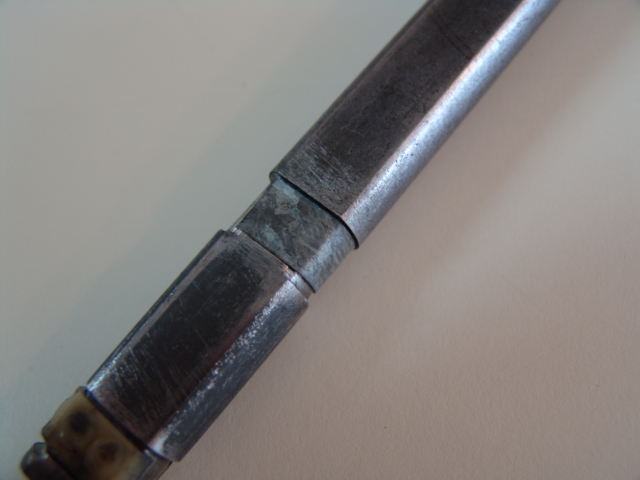
Before putting the slip joint back together I greased the shaft and
nylon clips with silicone grease. The
tight fit required tapping the inner shaft into the outer shaft.
Keep in mind that any force applied forward on the shaft is transmitted
directly to the pinion shaft in the steering rack so use caution. So far the
slip joint repair has worked out very well with no radial play. Just
removing the minimal free-play
made a big difference on how the car feels and steers on the road.
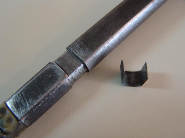
View
of the clips and shims.
The shim shown
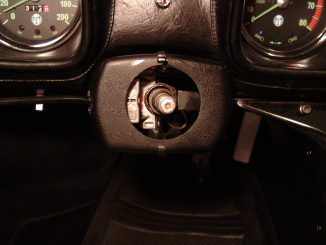
I
used the coat hanger tool to hold the column while hooking up the terminal and
turn indicator. Views of the
column assembly being installed back in the car.
It takes a little work to get the right and left cover to line up so the
male and female parts interlock
correctly. It is
helpful to leave
the back column mounting bolts loose while you get the two cover halves positioned
and then tighten the bolts.

The turn indicator on my car has never canceled correctly after making a turn. While I had the steering wheel off, I noticed that the red indicator cam was in the wrong position when the steering wheel was centered.
The
Lecarra wheel can be located on the hub in eight different positions but the
hub only has two different cutouts to key the red turn indicator cam 90
degrees apart.
The wheel was positioned incorrectly on the hub so that the key was in
the one-o-clock and seven-o-clock position rather than the nine-o-clock
position required for the cam to work with the turn indicator pawl.
I removed
the wheel from the hub by removing the nine bolts and nuts so I could reposition
the hub.
For some
odd reason the keys on the hub cannot
be positioned exactly at nine-o-clock but it is pretty close.
Ideally
the center of the red indicator cam should be centered with the turn indicator
pawl.
The width
of the red cam that works with the pawl is designed so that you can set the
turn indicator lever for a turn and then move the wheel back and forth a few
degrees without the turn indicators canceling, e.g. making a lane change
before turning.
The images below show the eight wheel positions on the hub, the red turn indicator cam placed close to nine-o-clock and the keyway in the hub.