At
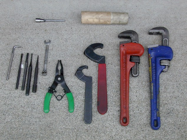
the left are a variety of prying tools, custom chisels (narrowed on a bench
grinder to fit into the slots machined into the rack and the tie rod nut), a
pointed punch (most useful for lifting up on the indented portion of the ring
in the center, rendering the ring circular again), and a flat punch (used to
stake the ring during reassembly).
Alongside are a specialized adjustable pin wrench, and an adjustable spanner,
which are used to remove and install the tie rod. Should you choose not
to buy those tools, simple pipe wrenches can be substituted, although they
will mangle the locking ring and tie rod.
The next tool is actually a sprinkler tool by Rain Bird, which happens
to be absolutely perfect for removing the spring-loaded plunger from the rack
housing.
At the top is is a 10/24 tap welded to a 1/4 inch drive socket (for
tapping a hole in the rack housing if the secondary type of replacement
bushing is used) and a bushing malletizer (PVC pipe turned on a lathe to match
the inner diameter of the rack housing, and set up to sink the new bushing to
the proper depth). A deep-wall socket is an acceptable substitute, but
you must take care to drive the bushing to the proper depth.
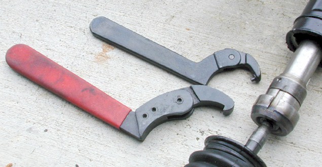
The
pin wrench is made by J.H. Williams, which is a 19th century tool manufacturer
that recently has been absorbed by Snap-On. Both Williams and Snap-On
offer similar tools, with the Williams tools being quite a bit less expensive.
I was able to download their PDF catalog, find the appropriate (smaller)
wrench, and buy it from a local distributor for only about $20!
The hook spanner should be available locally, but J.H. Williams sells them
too.
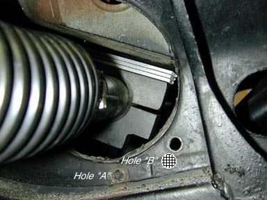
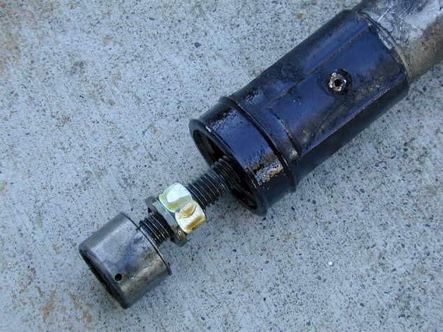
The above photo clearly shows the relationship between (from top to bottom)
the rack housing, the rack, locking ring, tie rod and rubber boot.
Ordinarily, the end of the boot is clamped into the groove in the end of the
rack housing, so all these guts are hidden from view.
This photo clearly shows how the locking ring is peened into a groove
machined into the threaded portion of the tie rod. Disassembly requires
prying up that peened portion, then carefully turning the locking ring and tie
rod in opposite directions to free them up from one another, then unthreading
them to remove them both from the rack.
Barely visible on the right side is a second indentation on the other end of
the locking ring, where it is peened into a groove on the rack itself.
It is especially important that this indentation is removed fully, because
otherwise when you remove the locking ring, it will mangle the threads on the
rack, potentially compromising safety.
The tool for the Pantera rack is the top one pictured on page 30 of the wrench
section of the J.H. Williams catalog; you can download it here:
http://www.bahco.com/us/pdf/williams/wrenches.pdf
Part
number is 0-471 and the cost was $20.01. Such a deal!
Unfortunately, Williams doesn't sell directly to the public; you have to call
their customer service hotline to find the nearest distributor:
Customer Service
Continental U.S.A. and Canada
Phone: 706-569-1002
800-423-2062
Fax: 800-367-8318
International Phone: 706-563-9590
International Fax: 706-563-1820
Buying this tool is money well-spent, I believe, if you ever envision doing
more than one rack. The pipe wrench method works fine too though, and
since all these parts are hidden under the boots, nobody will know you
brutalized the thing.
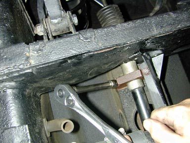
The job of disassembly begins with removing various bolts with a 13mm socket. There are three bolts with nuts which secure the rack support (sheetmetal piece to the right of the rack housing) to the chassis, and four bolts (shown here) which thread through the rack mounting clamps directly into captured nuts welded to the back side of a main chassis structure. If you should happen to snap those nuts off inside the chassis, you are doomed. Sell the car! To prevent this, spray Liquid Wrench liberally into the nooks and crannies in the chassis piece, with the faint hope that some will get onto the end of the bolt.
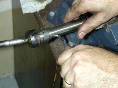
The steering coupler must be removed from the rack pinion. Often it’s rusted in place, so plenty of Liquid Wrench must be employed here also. After removing the pinch clamp bolt and nut, hammer a sharpened screwdriver into the pinch clamp to hold it slightly open, and tap against the coupler from beneath the car with a hammer and a long punch. Tap the coupler back towards the rear of the car until it slides off the pinion input shaft.
Here are the rack mounting clamps as seen in the photo above. The late L-model cars (and later cars, presumably) came with about a 10mm shim between the clamps and the chassis of the car; this shim was developed and used on the factory Group 4 and GT3 race cars to improve bump steer characteristics. Since this 1972 L-model Pantera was lacking these shims, we fabricated our own using aluminum strip measuring 1/8" x ¾". Three layers of shim equals almost exactly 10mm, and provides great adjustability in the event the suspension geometry is changed at a later date.
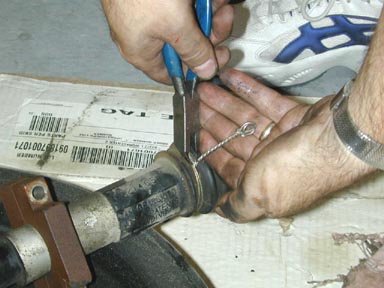
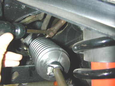
The factory boots are secured with twisted stainless steel wire. Most earlier cars had very special, unusually thin hose clamps instead of wire securing the boots; if these are in good shape they can be reused. Note that they are slightly too large in diameter, and even when fully compressed, the boot will probably be loose enough to rotate by hand. Use a pair of dykes to snip the wire close to the boot and discard it. Be careful if you plan to save the boot! The presence of this wire is absolute proof that the rack boot has never been removed before.

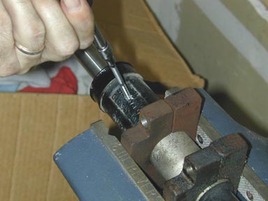
The tie rod is threaded onto the end of the rack, and is secured with a smooth lock ring. The two are peened together and the lock ring is also peened into an indentation in the rack. You must un-peen both places to remove them. It is especially important to make sure you thoroughly un-peen the indentation into the rack, because the steel is rather soft, and an other-than-round lock ring will seriously demolish the threads if you have to muscle the ring off of the rack. The ring should turn reasonably easily; if you have to force it, STOP and attend to your un-peening duties! Here a customized chisel is used to start un-peening.
An L-shaped prying tool can be
used to perform this job but
a small,
round punch is the most effective means of raising the indented portion of the
locking ring without damaging it. As these punches are hardened, they
should not be used as prying tools; rather, the punch should have sufficient
taper to lift up on the indented portion of the ring as it is gently tapped
with a hammer.
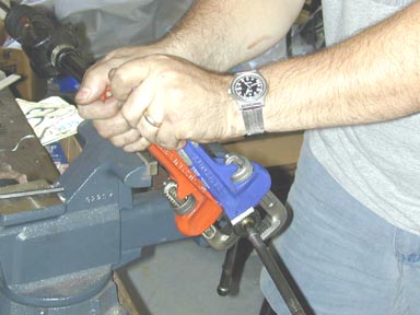
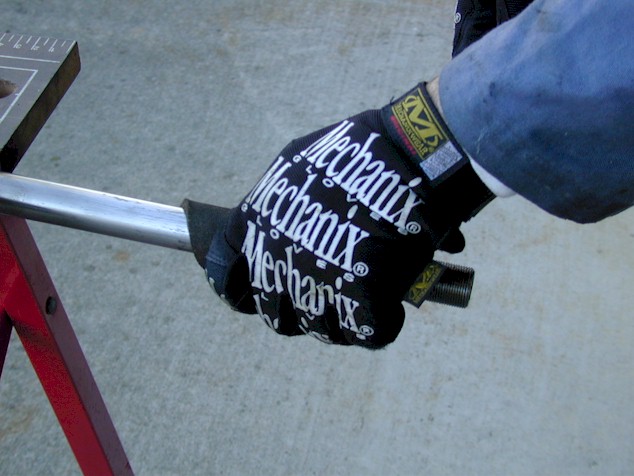
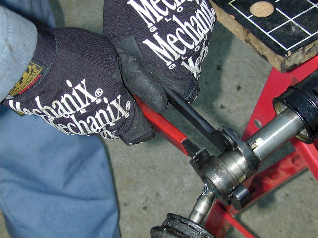
If you do not have access to the proper wrenches as shown in the tools image, pipe wrenches can be substituted, but recognize that they will mar and damage the exterior surfaces of the locking ring and tie rod. With the un-peening complete, two pipe wrenches are used to break the tie rod and lock ring free from one another. Turn the tie rod to the left and the lock nut to the right, facing the rack. Place the wrenches as shown and then pinch them together to get maximum torque. Avoid spreading the wrenches so that you are placing undue pressure upon the rack itself.
If
the rack has been allowed to run dry for any length of time, it is likely to
suffer extensive corrosion, as well as severe build-up of dried-out oil which
turns into a very stubborn solid substance. Attempting to install a rack
bearing with any obstruction on the rack will result in the rack actually
binding up. You do not want to go through the whole installation
procedure, get everything buttoned up and then discover that you can't turn
the steering wheel! Fortunately, dismantling the rack for cleaning is a
simple affair once the rack is removed from the car.
The rack pinion is supported by two ball bearings. In extreme cases,
these bearings can be rusted beyond salvation, and they are impossible to find
through conventional bearing supply sources. Fortunately a few of the
Pantera vendors in the USA have found a source. These bearings should be
removed, and thoroughly greased prior to reassembly.
The rack is pressed against the pinion by a steel plunger which is compressed
by a small spring. Often, removing the cover and spring will enable the
plunger to fall free; in this particular rack, the O-ring seal was excellent
and the plunger didn't want to budge. If this is the case, go to your
local hardware store and buy a Rainbird sprinkler tool, which is
basically a pair of thin pliers with the jaw on the outside. This will
fit perfectly into the indentation on the plunger; squeezing and pulling will
easily extract the plunger.
Tension between the rack and pinion is controlled by the use of one or more
extremely thin sheet-metal shims between the spring's cover and the rack
housing. Remove the spring cover which resides at a 90-degree angle to
the pinion using a 1/2 inch socket, taking care not to damage the shims or the
spring.

Then
remove the bearing cover opposite to the pinion, again using a 1/2 inch
socket. A circular spacer resides between the cover and the face of the
bearing. Note that although the covers look very similar, the bearing
cover is slightly larger and thus they will not interchange. To pop the
bearing free, lightly tap against the opposite end of the pinion (where the
steering coupler was attached) with a plastic or wooden mallet. This
will drive the bearing out of the rack housing.
The pinion can not be removed until the rack is turned to the end of the
toothed portion, where a notch is cut in the face of the rack. It will
probably be impossible to turn the rack by hand, so use a pair of Vice-Grip
pliers (or a handy shift- or steering-linkage u-joint) to turn the
pinion. Be extremely careful not to damage the fine splines. Turn
the pinion so the remaining tie rod moves away from the rack housing, and the
toothed portion of the rack becomes visible. When turning no longer
moves the rack, you're there. Now, by maintaining the orientation of the
rack within the housing (it may want to rotate, which will cause the notch in
the rack to hit the pinion and prevent it from sliding out), gently tap
against the pinion, and it should pop out. The above photo shows the
notch in the rack lined up with the pinion and the bearing on the opposite
side.
Ideally, if you've gone this far, you should remove the rubber pinion seal
from the other side and replace it. These seals are another DeTomaso-vendor-specific
part, very difficult to find through conventional channels, but fortunately
cost only about $12 from the Pantera vendors. Should you elect to re-use
it, be especially careful not to damage it during removal and installation of
the pinion.

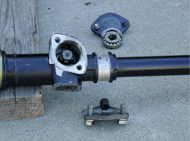
This shows the rack dismantled to the extent necessary to perform the job. At top is the bottom pinion bearing cover, spacer and bearing. The rack housing contains the upper bearing, and the plunger which presses against the underside of the rack. The rack itself is hardened only along the toothed portion (hence the discoloration) and still has the driver's side tie rod and boot affixed. Beneath that is the plunger cover, shim and spring, the pinion, and a handy U-joint I use to turn the pinion.
The
extensive buildup on this rack would have prevented free movement had the
bearing simply been hammered into position. Although it looks like
severe rust, this rack had considerable foreign matter stubbornly clinging to
it, but only mild pitting and no real rust.
The majority of the debris was removed using a gasket-scraper. The final
clean-up was performed using a Scotch-brite pad (steel wool also works
well.) Be advised that the rack itself is made of extremely soft steel
and is very vulnerable, so use care when scraping or filing.
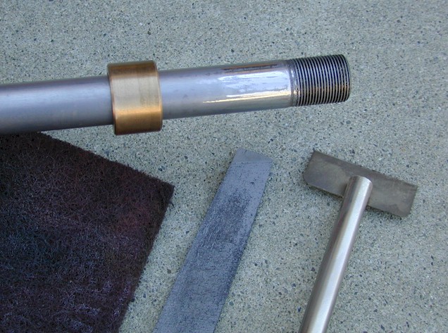
The end of the rack has a tendency to swell or mushroom when the threads are
cut; as a result, most bearings will slide over the threads but will not be
able to pass onto the shaft itself without some work. Carefully file the
sharp shoulder at the end of the threads, and perhaps the first inch or so of
the smooth portion of the rack, being careful to avoid filing on the threads
themselves. Periodically stop and test-fit the bearing. The goal
is for the bearing to slide up and down the rack without binding, yet not to
the point where there is unwanted slop.
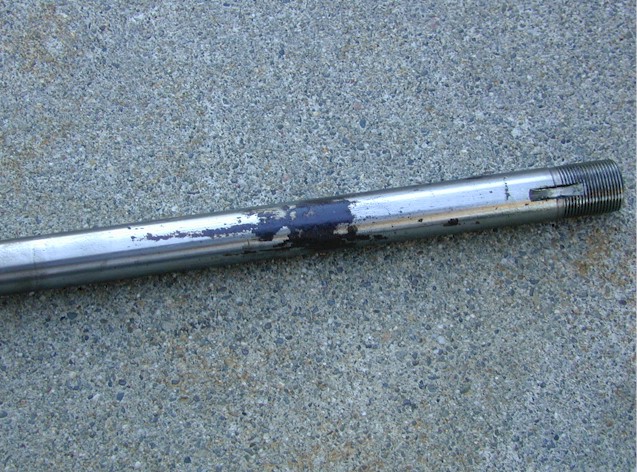
Frequently, there will be corrosion and residue on the rack itself. This is a combination of rust, dried oil and decomposing nylon from the bushing. If the rack was rebuilt on the car, this residue would prevent the rack from operating smoothly (or at all!). This shows the importance of fully dismantling the rack to service it.
The
preferred technique is actually to remove the old bushing and replace it,
rather than using the other style of bushing which supplants the stock,
worn-out one.
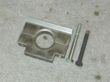
In order to remove the old bushing, first the set-screw must be removed.
Then, a very thick, strong washer is ground down to the appropriate
diameter. The washer should be larger in diameter than the inside of the
bushing. Grind two flats on it, which will let it slide vertically
through the bushing. Once it's through, it can be rotated and it will
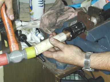
then 'capture' the inner edge of the bushing. Using a long piece of
all-thread rod with a nut a few inches from the end, insert the rod from the
driver's side of the rack, through the center of the washer, and then
liberally whack the end of it, to drive the bushing out.

Using a Scothbrite pad, carefully sand the surface of the rack, to remove all residue. Slide the new bushing over the rack and make sure that it moves freely; there should be some clearance between the inside of the bushing and the outside of the rack, because the bushing will 'shrink' somewhat when it is pressed into the rack housing.

A very slight bevel should be put on the edge of the bushing, to make it easier to insert into the rack housing. The bushing will index against a step inside the rack housing, so if you make your bevel too large, it might allow the bushing to travel too far, or actually be compressed by the rack housing when the bushing is driven into the step. Test-fit the bushing on the rack housing and only put enough bevel on it to let it get started into the end of the housing.
You will need to use a mallet and a piece of pipe, or a deep-wall socket to drive the new bushing into position. There are two different-sized bushings on the market; most vendors sell bushings which are designed to replace the stock bushing entirely. (There are a few vendors that size their bushings about .020" larger; these are designed to augment (rather than replace) the stock bushing. The procedures for using these bushings are at the bottom of this page.) Once the new bushing has been fully seated into the rack housing, carefully use a very small punch, insert it through the threaded set-screw hole, and with a hammer make a clear indentation in the center of the exposed portion of the bushing. Then, using a very small drill bit, so as not to touch the threads on the rack housing, drill straight through the bushing. This will give the set screw a place to 'bite' into the bushing, without deforming it unduly. Use Loc-Tite to secure the set screw.

Although
the Pantera rack was originally filled with 90-weight gear oil, TRW (the
company that bought out Cam Gears UK, the manufacturer of the Pantera rack)
now recommends 0-weight grease, instead of oil. Although 0-weight grease
can be purchased in 10-gallon tubs, only a fraction of that is necessary for
this job. The nearest thing you can find at the retail level is CRC
Engine Assembly Lube, which is 0-1/2 weight.
With the new bushing installed, the teeth on the rack are liberally lubricated
with this grease; the bearings, and pinion, and the other end of the rack
where it passes through the bushing, should all be similarly lubricated.
When it's time to reassemble the rack, simply perform the above steps in the
reverse order. It is far easier to install the bearing with the rack
entirely removed from the housing. Remember to rotate the rack within
the housing so that the toothed portion faces away from the plunger, and line
up the notch to enable the pinion to slide freely. Once you've got the
pinion in place, slight pressure on the end of the rack will allow the teeth
to engage, and you should be able to then turn the rack side-to-side with the
pinion.
Be advised that if the hole that you drill in the bearing for the set screw
isn't deep enough, tightening the set screw will actually deform the bearing
and cause the rack to bind up. It's best to drill straight through the
bearing, so that the set screw will completely thread into the bearing.
This
photo shows the two spanners in use. The tie rod is threaded onto the
rack to the appropriate point, and then the locking ring is tightened against
it using the pin wrench. When finished, the peened portions of the
locking ring should once again line up with both the indentation in the tie
rod, and the groove machined into the rack itself. This is a good
quality check to ensure that you have tightened the tie rod to the appropriate
degree.