By Ralph Granchelli
Rgranchelli at esedona.net

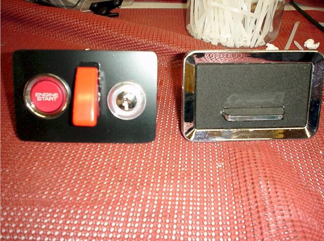
In this app note we will install a push button starter and a new key switch to replace the original switch on the steering column. I didn’t want to hack up the dash or relocate the hazard light switch so I made a panel to relocate it to the center console replacing the ashtray which was expendable to me.
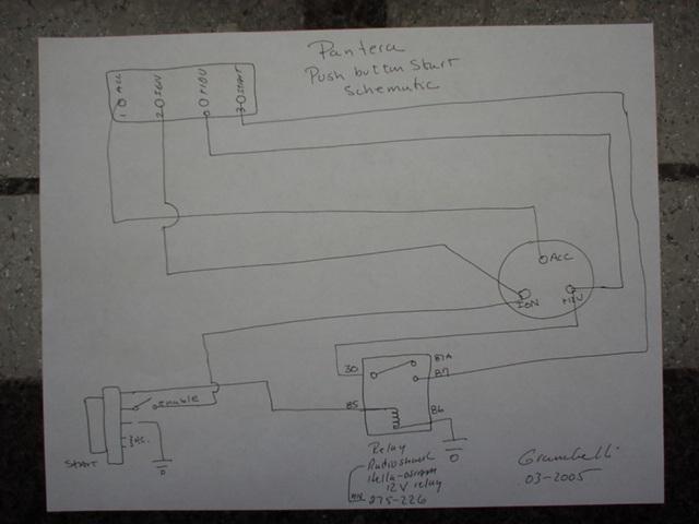
The schematic and wiring diagram are universal so it can be modified to put the start button wherever you want. Be aware that this modification eliminates the column lock and the key left in warning.
This set up will work particularly well in vehicles in which the fan, headlights and ignition system tasks have been off loaded to relays such the current load is not seen by the ignition switch. Additionally, we will now off load the starter solenoid trigger function to a relay.
First remove the steering column retaining bolts and Allen caps. Support the steering column from dropping down with a box to hold it at a height in which there is no strain on the under-dash directional and start wiring harnesses. Remove the screws that hold the trim over the ignition switch & the directional. Remove the left console access cover, shift knob, shift trim plate and screws that hold the console in place.
As the wiring changes from car to car, let’s define the connections to the under-dash connector.
With the battery connected and the ignition switch off, probe the exposed ignition switch terminals to find the main 12 volt line, hereinafter referred to as line (0). Identify which wires in all the following cases, (0 to 3) go to the under column four terminal block.
Now turn the switch to the accessory position and find the next line which has become powered, this is the accessory line, referred to as line (1)
Place the switch to the on position and find the next line to become powered, this is the ignition line, referred to as line (2)
The only other line left is the start line referred to as line (3).
These references will correlate to the lines on the schematic and wiring diagram to hook up to the under-dash connector. Make notes to the attached wiring diagram at the under-dash connector to reflect your wiring.
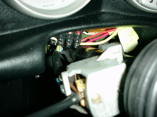
With the battery disconnected, remove the four ignition switch wires from the under-column terminal block. There will be two security bolts holding the ignition switch in. Take a sharp punch and drive the bolts in the counterclockwise direction and they should come right out. Remove the switch. Caution: The steering wheel ignition key locking mechanism must be completely and permanently removed from the car.
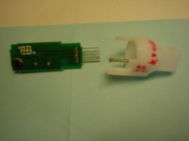
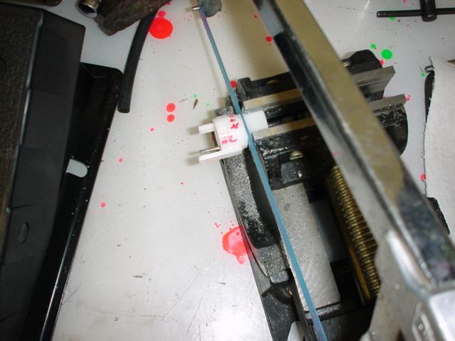
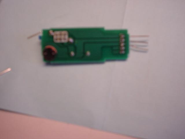
The starter switch is a Honda S2000 starter switch. It can be procured from
http://hondacuraworld.com/Merchant2/merchant.mvc?Screen=PROD&Product_Code=35881-S2A-911&Category_Code=HS2000for less than $40.00. I disassembled the switch to cut the connector cover off so I could solder to the switch. Upon reassembly of the switch, you need to make sure you press the start button fully down one time to seat the micro-switch to the start button cover. After soldering, use shrink wrap to protect everything.
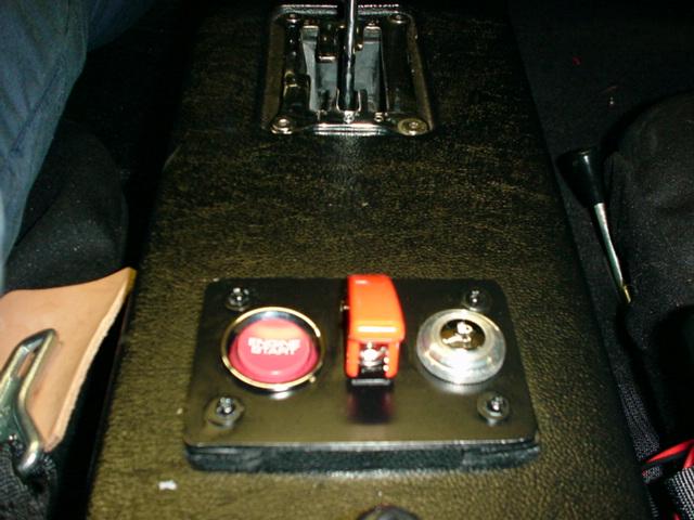
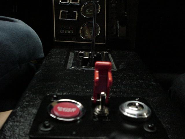
The starter enable/disable switch activates the push button starter. It has a spring loaded cover which turns the switch off by pushing the cover down and then disables the start function. The switch is an s.p.s.t. switch with a spring loaded cover. I got it at the Auto zone.
I picked up a motorcycle ignition switch from Dennis Kirk.
http://www.denniskirk.com/jsp/product_catalog/Product.jsp?skuId=200729&store=Main&productId=p200729&catId=4&leafCatId=41205
It has an accessory position and an ignition. position. Providing you have installed relays to handle many of the high current tasks this switch should handle it. You can put a DC ammeter in series with each of the four lines to look at the peak current drawn by turning accessories on. This will help you determine what size switch you will need for your specific application.
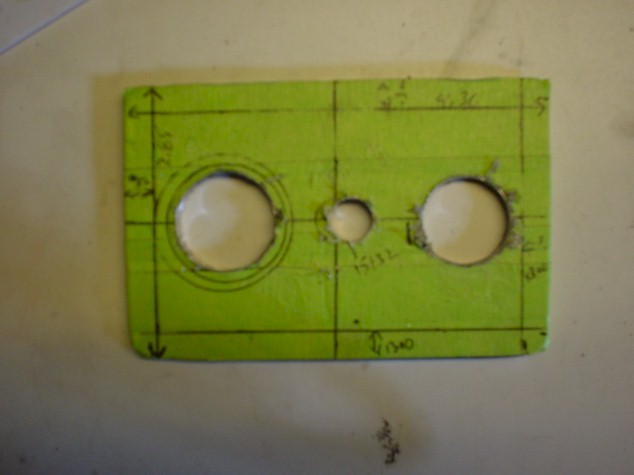
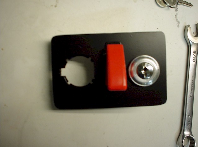
Make a panel: I used 3/16 " aluminum plate. You can see a template with rough dimensions to use as a guide. You will need to measure the size of the opening in your console and place the retaining screws such that they clear the console. Make two backing plates and put riv-nuts in them to hold the panel firmly in the console. Either paint the panel with flat black paint or polish the panel. On the back of the panel where it rests on the console I put the soft side Velcro strips to protect the console. Due to the depth of the start switch, I was concerned the wires would rub on the shift linkage. I made a 3" x 3" shield which I screwed over the linkage to shield the wires. I also made a spacer plate to elevate the switch panel an additional 3/16 ".


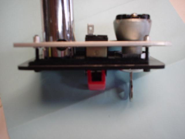
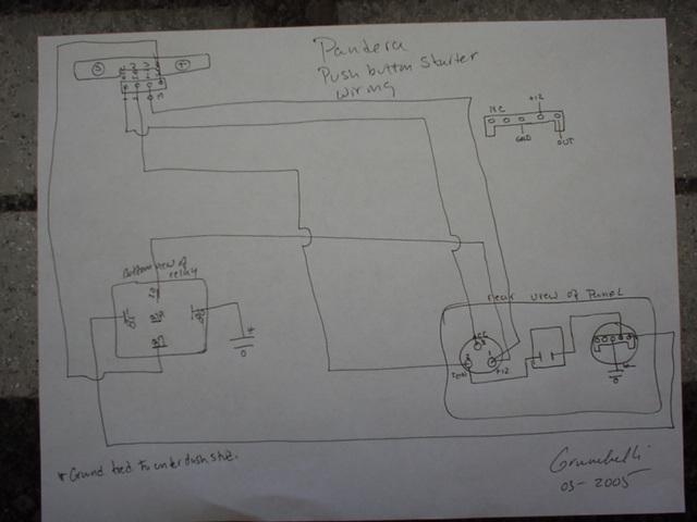
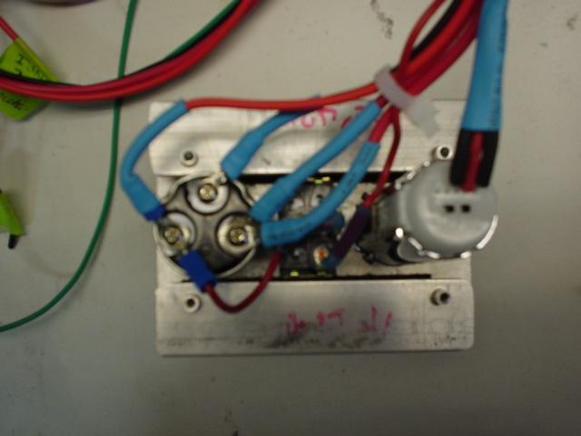
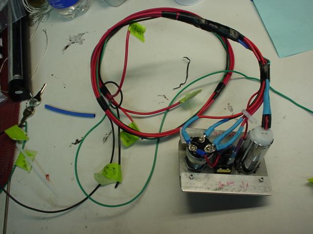
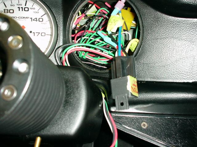
Assemble the panel and wire it as per the diagram and photo. Make a wiring harness running from the panel, under the console, under the dash and coming out the tachometer hole in the dash. I put the relay to trigger the start solenoid behind the tachometer. The start wire follows the main 12v line to the terminal block. The balance of the wires are routed to follow the same path.
Test the circuit. With the relay out of the socket, turn the ignition switch on. The ignition should come on and the alternator discharge light should come on.
Place the enable/disable switch in the on,(start) position.
Probe the relay socket with a DVM. There should be 12 volts on pin 30 as it is hard wired to 12 volts.
Now push the start button, there should be 12 volts on pin 85 only when holding the start button down. Release the start button and confirm there is no voltage present on pin 85.
Providing everything checks OK, turn the ignition switch off. Put the relay in the socket. Make sure the car is in neutral. Verify the start function to start the car.