Classic Ammeters
Classic ammeters utilize a standard coil-of-wire/spring/permanent magnet style meter movement designed such that 50 millionths of an amp passing thru the coil will cause the meter to deflect to full scale. The coil-of-wire part of the ammeter has considerable resistance and this makes the meter very versatile. By placing a resistance which is much lower than the resistance of the coil-of-wire in parallel with the meter movement a current divider will be created. The majority of the current to be measured will flow thru the low resistance path, and a much smaller portion of the current to be measured will flow thru the meter movement coil-of-wire. If the low resistance path is a precision resistance, the relative current thru each path can be quantified and the circuit can be designed to indicate any desired magnitude of current. The precision resistance in parallel with the coil type meter movement is termed a "shunt" because it diverts the majority of the circuit current around the meter movement.
Pantera Ammeter
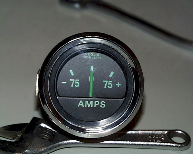
The Pantera Veglia ammeter is not a classic ammeter. The Veglia ammeter does not have a coil-of-wire style meter movement and does not have a precision resistance shunt.
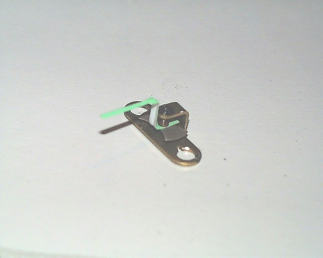
The Veglia ammeter contains and indicating needle connected to a bowtie shaped permanent magnet. This assembly contains no coil-of-wire and no springs.
The indicating needle/bowtie magnet is mounted over a Zero Magnet which, if no current is flowing thru the ammeter, will cause the needle to indicate Zero. The strength of the Zero Magnet also sets the full scale indication sensitivity of the ammeter.
The terminals of the Veglia ammeter are connected by a solid piece of brass thru which all the battery charging/discharging current flows. This current creates a magnet field around the piece of brass proportional to the magnitude of the current flowing and at an angle of 90 degrees to the magnetic field of the Zero Magnet. The bow tie shaped permanent magnet attached to the indicating needle will move in response to the field created by the current through the piece of brass. Which direction and how far the needle moves from Zero will be determined by the vector sum of the magnet field of the Zero Magnet and the magnetic field created by the flow of current thru the ammeter. (Note: Take note of the small notches in the terminal holes of the brass strip.)
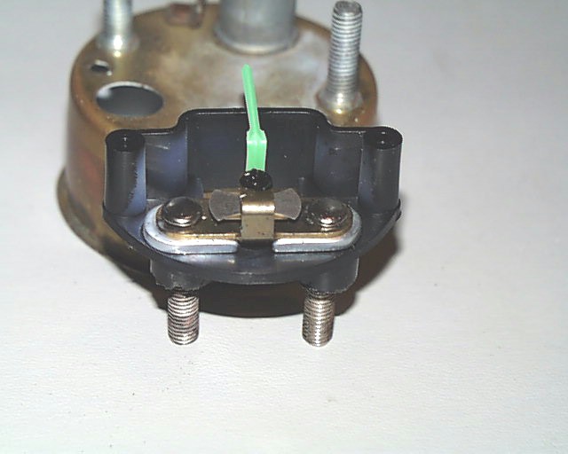
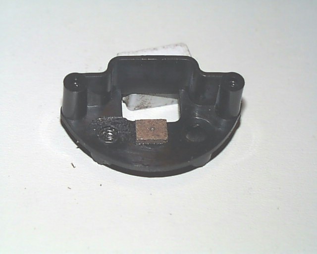
This is the complete ammeter mechanism, ready to do business. The Veglia ammeter mechanism is inexpensive and simple to manufacture as it has no coil-of-wire, no springs, and no precision shunt. The non-magnetic aluminum spacers compensate for the thickness of the Zero Magnet.
Ammeter Problems
Heat
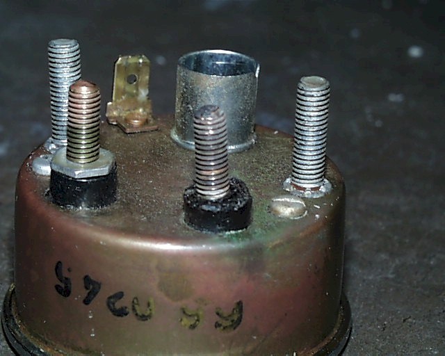
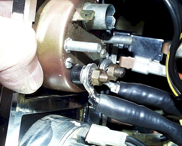
Excessive heat can occur due the basic mounting of the ammeter components. Note that the right hand terminal has been overheated to the point that the thin terminal retaining nut is recessed into the plastic of the terminal insulator and the terminal is now off center. The head of each current carrying terminal has a raised spot which fits into a small slot in the brass bar part of the needle mechanism. This interlocking feature enables the terminals to be securely tightened using the thin nut seen on the left terminal above. If the terminal is not locked in place on the brass bar, it cannot be securely tightened and a poor electrical connection will result. A poor electrical connection with a resistance of 0.1 ohms will dissipate 423 watts with 65Amps flowing. If you had a 0.1 ohm resistance in an ammeter joint and were using the engine to charge a dead battery, the ammeter (any ammeter) would definitely get hot. The right hand terminal above has been hot enough to deform the locating insulator.
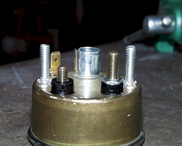
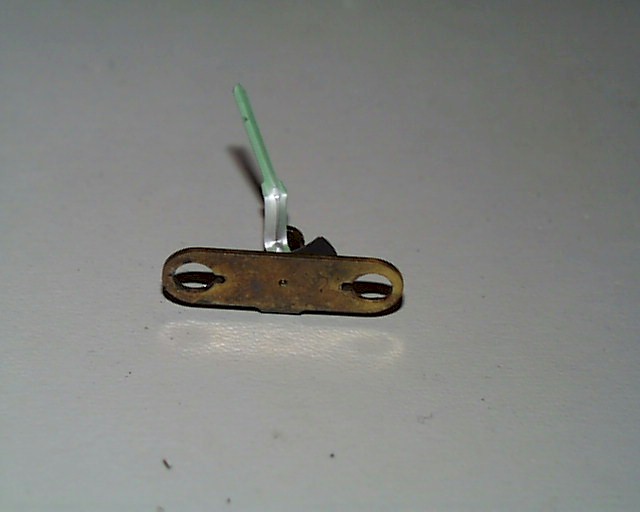
If the thin nut is removed from a terminal, the terminal can drop out of the brass bar as shown above. When the terminal is pulled back up, you must slowly rotate the terminal until you feel it lock in place on the brass bar such that it will not turn. Thread the thin nut in place while being sure that the terminal remains locked.
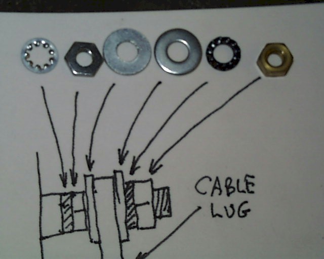
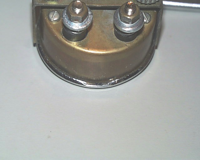
In order to insure that the terminals are adequately secured to the ammeter, install the improved hardware stack up shown above. The first lock washer and nut secure the terminal to the ammeter mechanism. The flat washers clamp the cable under the second lock washer and nut. The terminals should never be movable. If you can cause your existing ammeter terminals to rotate by pushing/pulling on the associated ammeter cable, you have an ammeter waiting to get hot.
Shown above is the installation of the improved hardware stack up on the terminals of an ammeter. When using the additional components of the improved hardware stack up, the terminals have more than adequate length for secure installation of all needed cable lugs.
Needle Jitters and Unreasonable Current Indications
The root cause of the famous Pantera "ammeter jitters" is in the basic design characteristics of the ammeter and the charging circuit. Automotive battery charging is not a smooth, linear process. The charging system, which is very power efficient, senses the battery voltage and is constantly switching charging current into the battery to maintain the battery voltage at the desired level. The use of a current switching technique means that very little power is lost or heat generated in the charging circuit. The rate of the switching in the charging circuit is dependent on the electrical and physical components in the voltage regulator, the electrical and physical components in the alternator, and the engine speed. The Veglia ammeter is summing two magnetic fields and, other than a small amount of friction in the needle pivots, has no damping mechanism to slow the speed with which the indicating needle can move. The Pantera "ammeter jitters" are simply the ammeter trying to follow the charging current pulses into the battery.
Classic ammeters contain coils consisting of many turns of wire which effectively damp out sudden changes of current. But the movements of classic ammeters typically pass only 50 millionths of an amp at full scale. A coil with sufficient turns-of-wire to damp out the Pantera charging pulses and still pass the 65A charging current would be quite large and weigh many pounds.
In order to eliminate the "ammeter jitters", some owners have added "shunts" consisting of two lugs and a short piece of wire connecting the ammeter terminals. This will reduce the current thru the ammeter and the magnitude of the "ammeter jitters" will also be reduced. How much the jittering will be reduced will dependent on the actual condition of the all the electrical connections in the ammeter and the condition of the Zero Magnet.
If the magnetic field of the Zero Magnet is at full strength, all the electrical connections in the ammeter are clean and secure, and an external "shunt wire" with a resistance equal to that of the internal brass bar is connected between the ammeter terminals, the sensitivity of the ammeter indication will be cut by one half. This is because half the current will flow thru the ammeter and half will flow thru the "shunt wire." Since the condition of the Zero Magnet is unknown and the state of the internal electrical connections is surely less than perfect, "shunting" the ammeter must be done by "cut and try". The amount by which the "jitters" are reduced is the same amount as the ammeter full scale sensitivity is reduced.
Unreasonable charge/discharge current indications and extremely high needle jitter can be caused by the Zero Magnet. The Zero Magnet is a critically import component in the functioning of the Veglia ammeter. The Zero Magnet causes the indicator needle to point at Zero when no current is flowing. The field strength of the Zero Magnet sets the ammeter full scale sensitivity. If the strength of Zero Magnet has decreased with time, or the magnet has been damaged, the ammeter may point to Zero when no current is flowing but may be extremely responsive to the field created by the charging current. A Zero Magnet with a weak magnetic field will amplify the excursions of the "jitters" and cause the ammeter to indicate unreasonably high charging/discharging currents.
Ammeter Disassembly
A gap exists in the back of the trim ring indexed by the ammeter terminals. The ammeter can be disassembled by using a very small screwdriver to pry the trim ring away from the vertical part of the body of the ammeter starting at the gap. By prying in very small increments and making several passes around the perimeter, the trim ring can be positioned clear of the ammeter body. Always pry away from the vertical part of the body of the ammeter and you will not break the glass face plate.
Remove all the terminal hardware and the two screws adjacent to the terminals and the internals of the ammeter may be withdrawn from the case.
While you have the ammeter open, verify that the rivet holding the lighting ground lug to ammeter case is tight.
When reassembling the ammeter, install the lock washers and nuts which hold the terminals to the meter mechanism. Verify that the terminals are locked to the brass strip. Insert the meter movement into the body of the ammeter. Install the two screws adjacent to the terminals. Install the remaining terminal hardware. Clean the glass face plate and the face plate support ring and place the glass face plate, support ring and meter movement/case into the trim ring. Index the gap in the trim ring to the ammeter terminals.
In order to crimp the trim ring to the ammeter body, use a piece of rigid material to protect the front of the trim ring and the glass face plate. Use a small pair of pliers to grip the rigid material and the back of the trim ring. Bend the trim ring toward the body of the ammeter. Do this bending in very small increments as you work around the perimeter of the ammeter. After several passes around the perimeter, the trim ring will be secured to the ammeter body. If this is done correctly, the front of the trim ring will be unmarked by any tools and the glass face plate will not be broken.
Acknowledgements
My thanks to Mike Drew for loaning me an ammeter I could disassemble to discover its internals and take the necessary pictures.