By Ralph Granchelli
rgranchelli at esedona.net
The original carbureted 351 Cleveland fuel delivery system as supplied from the factory was not designed for optimal performance. While there are many aftermarket carburetor options which will provide significantly improved performance, tuning becomes a significant challenge. Even after spending countless hours with a myriad of jets dialing in a new carburetor, that setting is only valid at a specific altitude, temperature, atmospheric pressure, phase of the moon etc. Additionally, carburetors are sensitive to vapor lock, starting problems, flooding, and fuel starvation.
Fuel injecting the Pantera provides ease of starting and improved drivability under most all operating conditions. Additionally fuel injection provides altitude & temperature compensation. There are many fuel injection systems available. Mechanical and electrical, throttle body and port fuel injection.
This article deals with fuel injecting the Pantera with the Holley Commander 950 PRO electronic, narrow-band, 700 CFM throttle body fuel injection system. This system coupled to the Crane street / race distributor & Hi-6 multi spark CDI provides a significant improvement over the factory solution. The components are reasonably priced and reliability is high. Full system implementation can be achieved in the vicinity of $2,000 for parts plus your labor. The throttle body fits any intake manifold with a Holley footprint. Tuning is via your laptop with the Holley supplied software.
The system can be installed and tuned by anyone with good mechanical & electrical skills. The system as depicted here provides programmable ignition advance through the Crane street / race distributor. Real time, computer controlled, "ECU" spark control can be achieved by using a Ford TFI type distributor or a GM HEI type distributor in a Ford form factor utilizing the 7 pin computer controlled HEI module. I have successfully used this implementation in other vehicles. However in the Pantera, due to space limitations, the Crane small cap distributor is advantageous and provides great performance.
The major components required for the conversion are as follows:
1. Holley commander 950 Pro TBI EFI system, Stock number 950-22s, available from Summit, Jegs Etc. Appx. $1350
2. Crane street strip programmable small cap distributor PN CRN-1000-1606 Appx. $320
3. Crane LX92 Race coil PN 730-0892 Appx. $70
4. Modified fuel sender from Wilkinson – Appx $280
5. MSD tach adaptor # 8920
6. Crane HI-6 ignition CRN-6000-6440 $219.00
7. Weatherpak pin tool – SUM-900402
8. Weatherpak crimp tool – SUM-900401
9. Aeromotive 02712304 100 micron filter, goes between the fuel tank and the fuel pump
10. Aeromotive 02712301 10 micron filter, goes after the fuel pump
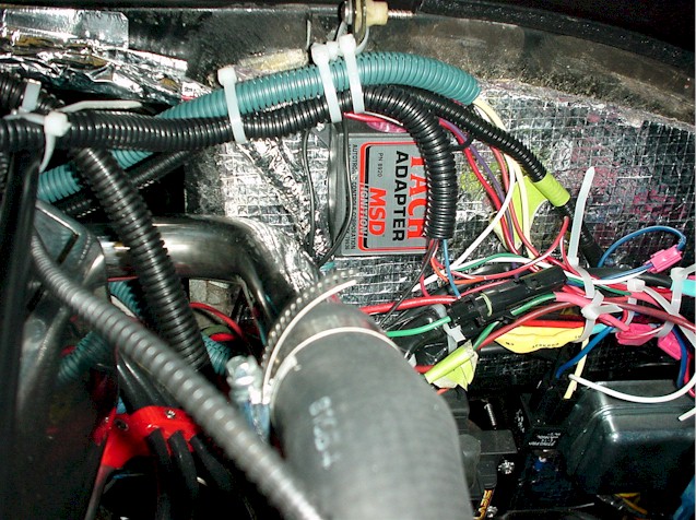
First we need to select the location for our components. The Holley commander 950 ECU fits directly behind the drivers seat on the interior firewall as shown.
 .
.
The Crane Hi6 CDI fits behind the passenger seat on the interior firewall as shown. The factory interior cover fits over both of these boxes and is not noticeable.
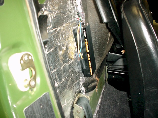
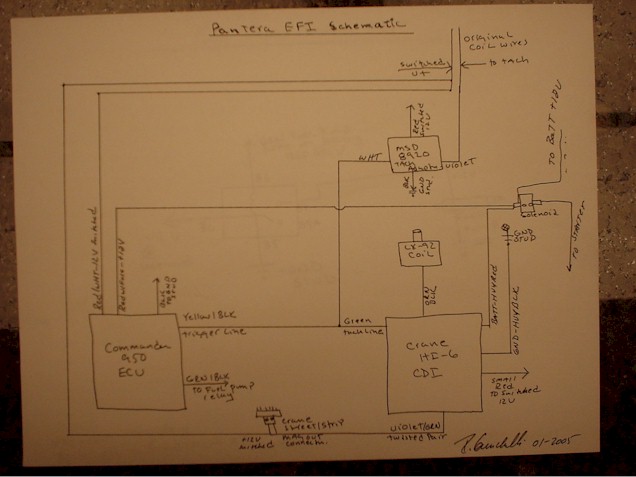
The crane Hi6 tach out line will be used to trigger the Holley ECU as well as to provide a signal to the MSD tach adaptor to drive the stock Pantera tachometer. See the Pantera EFI system schematic below.
It is important to mount these units in the passenger compartment to keep the operating temperatures of the boxes low to improve reliability. The reliability of semiconductor components is proportional to the ambient operating temperature & operating time. Wires are passed through the firewall isolated with rubber grommets. A grommet is supplied with the Holley unit, you will need to pick up one for the Crane hi6 wiring harness however.
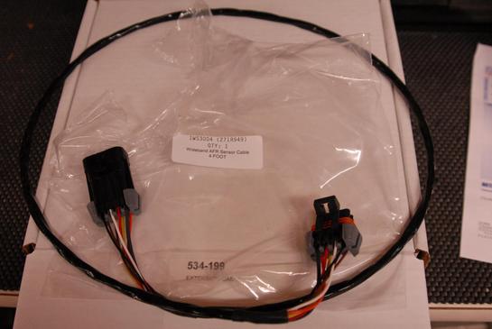
Additionally wiring of all the connectors for the Crane unit is with weather pak connectors. You will need a set of weather-pak connector tools available from Summit to release the connector from the outer housing to pass through the firewall and to crimp new connectors on the Holley units wiring harness. Use weather-pak connectors for all connections for high reliability. Additional connectors are available from Summit or Napa.
It is important to keep the coil secondary wire away from the low level twisted pair signal line from the distributor to the Crane hi6. The secondary high voltage line can cross couple to the low level signal line causing cross coupling and erratic firing. I shielded the coil pickup line using high temp wire tubing and foil tape and by keeping the distance as great as possible between these lines.
The coil will be mounted at the site of the original coil on the existing bracket. The MSD tach adaptor is mounted above the coil on the firewall.
The original coil wires are used to provide the switched 12 volt signal for the Holley and crane units. The other wire is used to send the output from the MSD tach adaptor to run the tach.
The high current 12v lines for the Holley ECU and the Crane CDI are available from the battery stud on the solenoid utilizing ring connectors. All grounds are tied back to the big ground stud beneath the solenoid mounting bracket.
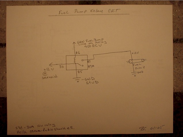
An additional separate relay should be used that will be triggered from the Holley ECU fuel pump line to run the pump from the relay. This will offload the current load to the relay and improve reliability of the ECU. See the fuel pump relay circuit schematic below.
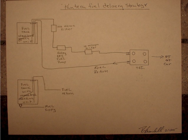
The fuel tank will have to be modified for a fuel return. The original fuel sending unit has the fuel supply line built in but no return. The original fuel supply line can be utilized for a return line however the fuel strainer which is in the tank will need to be defeated. The tank drain plug can be drilled out and a fitting can be fabricated onto the original plug for a fuel supply line. A pick up tube should be extended about ½ inch above the fitting to insure that sediment is not picked up by the tube from the tank. At a minimum, you should flush the tank. I had my tank out for a cleaning & painting, so I had Steve @ Wilkinson fabricate an additional 3/8 fuel supply line tube into a new sending unit for use in my tank. See fuel delivery strategy schematic below.
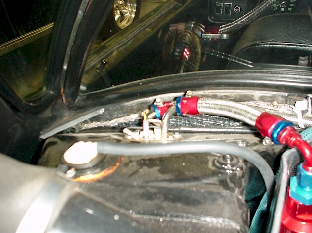
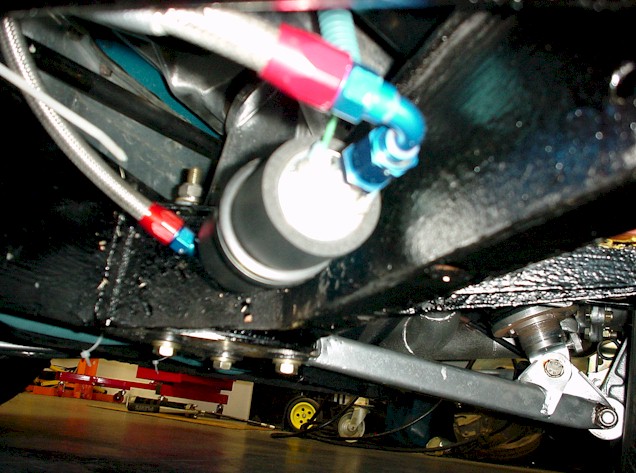
The fuel pump is located directly beneath the fuel tank as depicted in picture below. An Aeromotive screen type pre filter of 100 micron is utilized to trap any contaminants before the pump. An Aeromotive paper post filter of 10 micron is utilized after the pump to insure that the injectors do not get clogged.
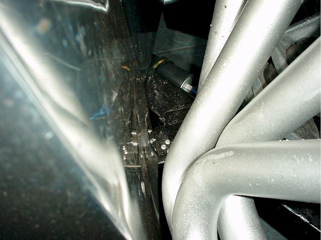
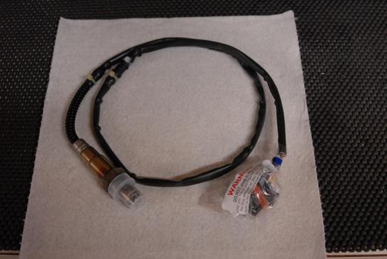
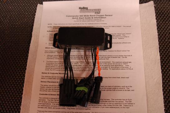
The oxygen sensor is located in the collector of the header. It is important to keep the angle of the sensor as depicted in photo on the left so as to keep the sensor from getting swamped out with condensation or fuel. We will be using a narrow band O2 sensor in this system and we need to integrate it into the exhaust system. I TIG welded oxygen sensor bungs in both header pipes at the header collectors. I use the Innovate wide band gas analyzer to tune the system. It is possible to tune the system just be reading the O2 sensor voltage on the Holley fuel map software however using the Innovate provides more accurate results. See Photo on the right for the wideband sensor placement for gas analyzer.


Hookup of all components is achieved using Earl’s fittings and braided fuel line. Any equivalent fuel lines can be used as long as they are rated for the pressures as put out by the fuel pump. The Fuel supply is less than Appx. 60 PSi and the return line is only a few psi. However since the visuals and reliability are an issue, braided stainless line and fittings work well.
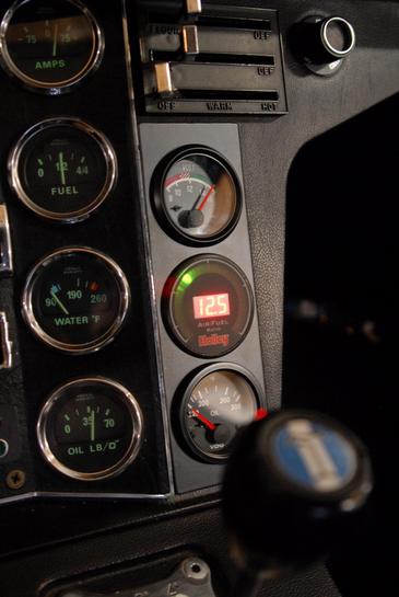
The coolant temperature sensor is placed in the swirl tank fitting. While not the perfect place for the sensor I did this to retain the stock gauge fuel sender in its original location. The down side to using the swirl tank is that the temperature rise is not detected by the sender until the thermostat opens. This could delay the system going closed loop. However this does not appear to be an issue based upon how my vehicle runs.
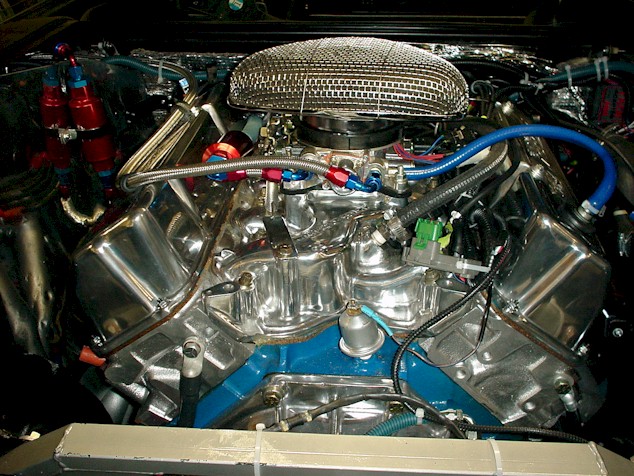
The complete system looks like this, and it all fits under the stock engine cover

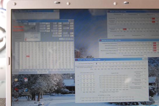
After installation of all components perform a system check out, load the Holley software into your notebook and hook up to the Holley ECU connector. Set up all of the initial parameters per the Holley instruction manual. A download is available here which includes my Holley Commander 950 file for use as a starting point. Final tuning is per the factory manual to your specific cars requirements. Download Commander950, by right clinking here and then save as to your computer. As continuous improvement is being made to this file, it will be updated from time to time and available on this site.