The Pantera Place
"Your de Tomaso
Connection"
Power Window Motor Conversion
By Todd Reid at rtaspl at aol dot com
Documented by Dick Koch at arkoch at earthlink dot net
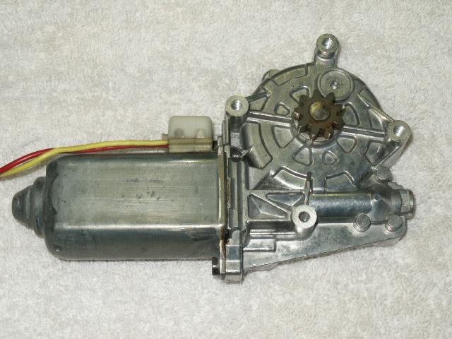
Todd Reid from Oklahoma City came up with a very simple and straight forward conversion for the stock window motors. His design uses low cost Ford window motors that have a sealed and very rugged gear box that draws about one fourth the amps the stock motor uses. Todd used window motors for a 1989-1994 Ford Aerostar minivan that can be purchased at various auto parts stores as a rebuilt item, ordered from an online recycler, or picked up at a local junk yard. These motors are particularly applicable to the Pantera since they do not require a drive gear end bushing to support the gear shaft.
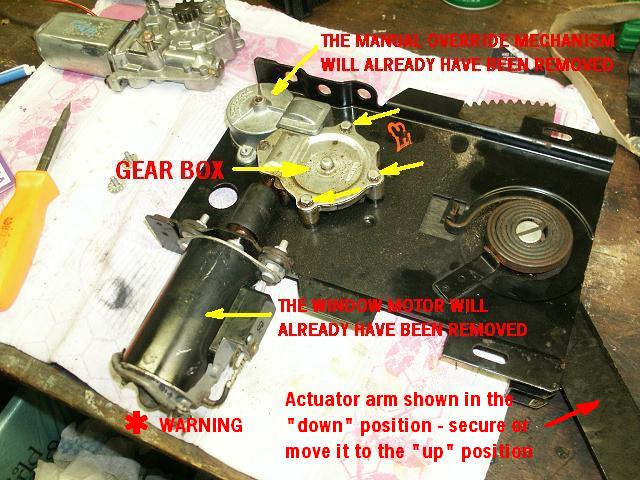
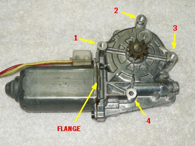
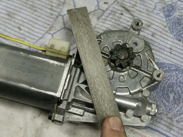
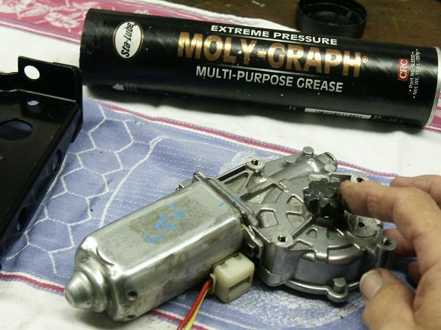
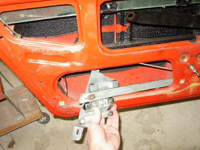
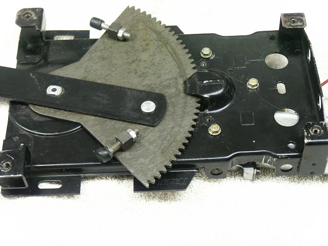
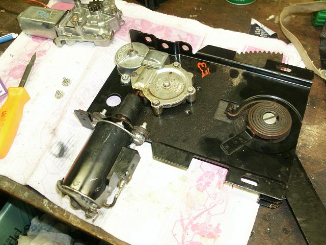
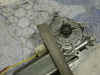
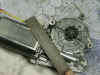
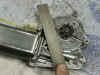
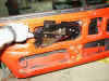
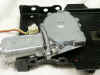
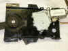
The conversion will take the stock Pantera window mechanism, as shown by the first picture above, and by adding the Aerostar window motor/gear assembly as shown in the second picture, to the much more compact and efficient assembly shown in the third picture above. The pictures above show the drivers side motor. The passenger motor is the mirror image of the drivers side.
This conversion requires only three holes to be drilled into the Pantera window regulator, with one of them tapped for a bolt, the Aerostar window motor filed to fit, and the bolts and washers to fasten the motor to the regulator. With a basic set of tools, anyone can do this conversion.
The Aerostar Window Motor
At NAPA the part numbers for the Aerostar window motor are:
* 49-8021 for the right (passenger) side
* 49-8020 for the left (driver) side
Important note: Be sure to get the four (4) hole motor mount version and not the three (3) hole version Ford went to in later years. At the auto stores you may get either one with the same part number.
The price will vary slightly from various stores such as NAPA, Pep Boys, or Auto Zone. A rebuilt motor from one of these sources will cost anywhere from $100 to $120 (includes price plus core charge). However, if you don't mind plying the internet or your local junk yards, you should be able to pick up a pair for $70 to $80. When you get the motor, try to get the SAE 12-24 x 9/16 mounting bolts that were used with it.
May 2006 Update:
I bought a set of Aerostar power window motors from a salvage yard here in Sweden a couple of days ago. I noticed that they are manufactured by Bosch with the following numbers:
Ford: F19B-1123395-AA
Bosch: 0 130 821 245Ford: F19B-1123394-AA
Bosch: 0 130 821 244Fredrik Gustavsson #7217
The Tools And Materials Needed
The basic tools and items you will need to complete this job include the following:
- Small and large Phillips head screw driver to take off the door panel
- Large slot head screw driver to remove the regulator pivot arm screw and arm rest upholstery buttons
- 10 mm wrench or socket to remove the regulator and window runner
- Flat file for "fine" tuning the motor mount height and general clean up
- Power Drill with 4 drill bits - 1/4", 3/16", 1/16" and # 25 (0.150)
- Hammer and Center hole punch to mark new mounting hole drilling locations in the regulator
- Two SAE 12-24 x 1/2 to 9/16" long (or SAE 1/4-20 x 1/2 to 9/16 long hex head bolts if 12-24 bolts are not available) with washers and external star lock washers, and One SAE 10-24 x 1.5" long bolt with three washers and one internal star lock washer.
- Tap for SAE 10-24 bolt hole (or a SAE 1/4-20 tap if 12-24 bolts are not readily available - SAE 12-24 bolts are not a common bolt size).
- Sheet of paper (preferably stiff like a vanilla folder), a square, and a tape measure to create the template
Additional tools and items you may want to have on hand are:
- Micrometer or finely graduated ruler
- Round bastard file for possible mounting hole adjustment
- Masking tape to hold the window up when you remove the window guide
- Grease for obvious reasons
- Mineral spirits and paper towels or rags for cleaning the regulator and window runner
- Black Magic Marker to dye the window brush strips
- Several Zip Lock bags to organize and store the parts as the door is dismantled
If the tools mentioned aren't available, do yourself a favor and buy them. Your local home fix-it store will have them. However, you can order them all through Harbor Freight at http://www.harborfreight.com/
The following items will cost you around $50 at Harbor Freight:
- tap and die set - item # 39391-0VGA
- center punch set - item # 647-6VGA
- wrench set - item # 3055-6VGA
- screwdriver set - item # 1694-0VGA
- file set - item # 40207-0VGA
- drill set - item # 40454-1VGA.
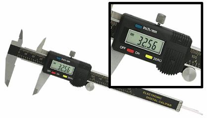
If you don't have a micrometer, get one. The digital micrometer that Harbor Freight sells, item # 47257-3VGA and shown in the picture above, will cost you $20 when on sale.
The Conversion Project - A Step By Step Approach
The conversion project involves various steps. Each step will be reviewed assuming the reader has no experience in that step. For folks that know how to remove and reassemble the door panel and window regulator assembly, skip A and C and follow B. For those folks that are the more mechanically inclined, create the template included in the instructions in step B, forget the rest, and have at it. For those that want to design their "own thing", forget all the instructions and good luck!
Disclaimer - Remember, Todd Reid shared his conversion and Dick Koch authored the documentation solely to benefit the Pantera "clan" . The documentation is offered as-is, and is to be used at the user's own risk. While the documentation is intended to be complete, there may be some aspects that are not clear to some folks. If not, let the documenter know and he will see if it is worth his time to include it.
And, "lo and behold" if there are some mistakes or inconsistencies in the documentation, don't start bitching at the documenter! Unlike some Pantera gear heads who think they know it all and lurk in the "hinterlands" waiting to pounce on the "littlest" inconsistency or mistake someone makes, the documenter will be the first to admit that he is not perfect. If you happen to come across something that is misleading or in error, just let the documenter know about the problem encountered and he will attempt to amend the documentation.
The conversion steps are:
A - Removal of the power window mechanism from the door
- removal of the armrest and upholstery panel
- removal of the window runner and regulator assembly
- removal of the stock motor and associated gear boxes from the regulator
B - Modification and assembly of the regulator and the new motor
- adjusting the height of the mounts in the new motor/gear assembly
- locating and drilling the new motor mount holes in the regulator and motor
- assembly and testing of the converted regulator assembly
C - Reassembly of the window mechanism in the door
- installation of the regulator and window runner
- adjustment of the window
- reassembly of the upholstery panel and armrest
The conversion can be made to be either "reversible" or "one way". The "reversible" conversion leaves the option of remounting the original motor/gear on the regulator. The "one way" conversion does not allow the option of remounting the original motor/gear on the regulator.
The conversion covered will be a "reversible" one that is a cross between both of Todd's original "reversible" and "one way" conversions. This "hybrid" conversion incorporates the best attributes of Todd's original designs.
Pictures taken while doing Todd's original conversion technique are shown at the end of this documentation. Todd's original "reversible" and "one way" conversion write up can be obtained at the Space City Pantera web site:
http://www.geocities.com/pocascp/Technical/Pantera_Window_Motors_Replacement.htm
The following conversion documented was done on a 1974 Pantera. Since the Pantera changed slightly from year to year, the specific details on some of the steps may differ for older or newer cars. However the changes in the areas that may affect this conversion will be minor and will not change how the actual conversion is made.
The pictures that are used in the documentation are from the driver side window motor conversion unless otherwise noted. Also, unless otherwise noted, the text for each step will apply to the picture above it if one is shown.
A - Removal of the power window mechanism from the door
Step A1 - removal of the armrest and upholstery panel
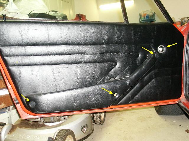
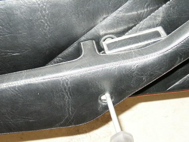
Remove the three upholstery buttons that cover the armrest screws and the manual override drive cover using a large slot head screw driver to gently pry them free.
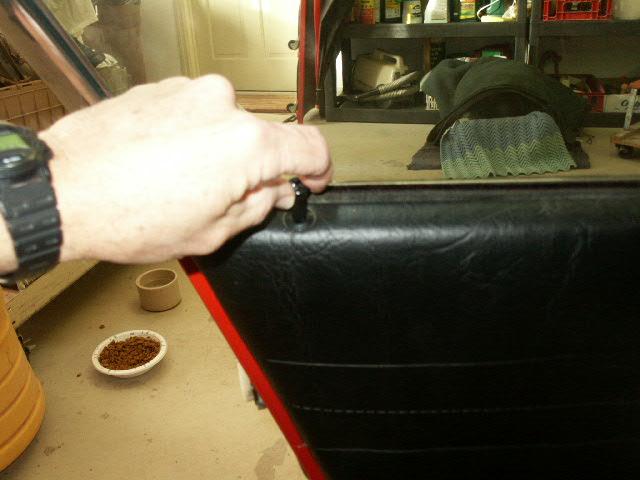
Then using the large Phillips Head screwdriver, loosen the three screws that secure the armrest and remove it. You don't have to take the screws completely out of the armrest. Next use the small Phillips head screwdriver and remove the door handle.
Unscrew and remove the door lock button
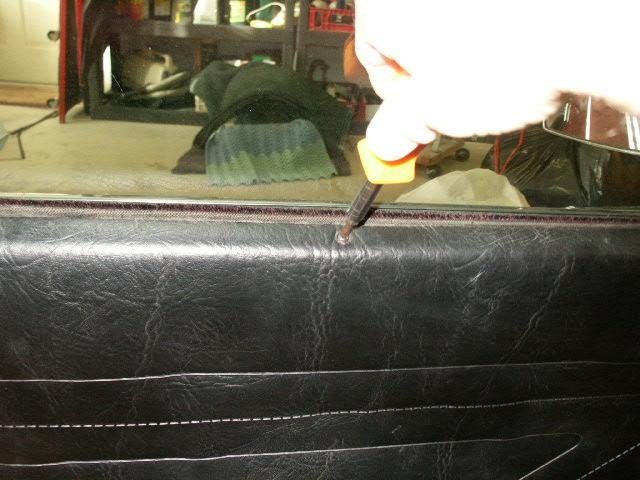
Using the small Phillips head screwdriver remove the nine (9) small panel screws that ring the door panel. Be sure to remove and save the upholstery washers that are used with these screws. Note that the two screws on the top edge of the door panel are longer than the rest.
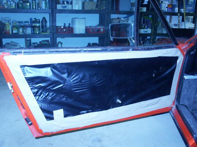
Remove the door panel and the protective liner that covers the inner door frame to reveal the window components.
Step A2 - removal of the window runner and regulator assembly
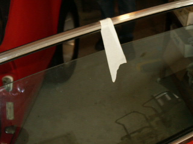
Position the window about 3" below the fully closed position and secure the window in that position with masking tape by taping it over the top of the door window frame.
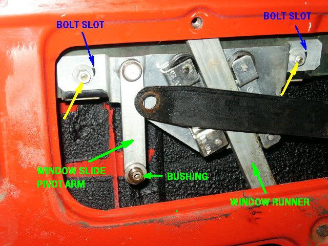
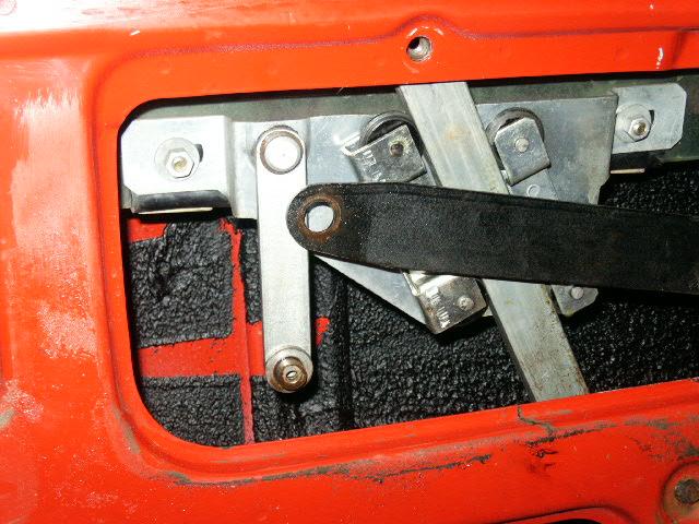
The regulator window actuator arm is attached to the window slide (which rides on the window runner) with a standard slot head screw. Remove the screw and all the associated washers. Be sure to remember the order in which these washers are sequenced in this assembly.
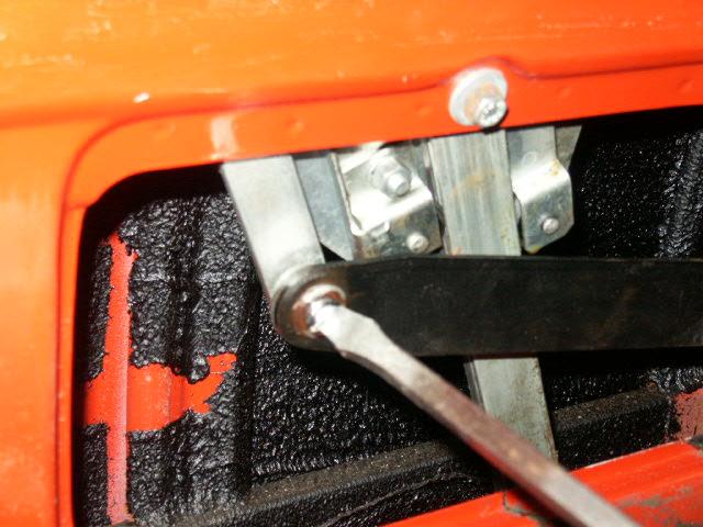
Remove the two (2) 10mm bolts that secure the window runner to the door frame (one at the top of the inner door frame and one on the outside bottom edge of the door )
Remove the two (2) 10mm nuts that secure the window slide to the window pane support clamps. Leave the rubber sleeves and the bolts in the window pane. Slip the window slide off the two bolts that hold it onto the window pane.
Remove the window runner and window slide mechanism from the door.
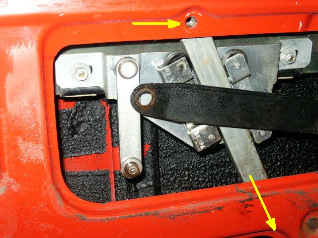
Put the regulator window actuator arm in the "window down" position by either using the power window button, or using the manual override and hand cranking it to the down position using the large phillips head screwdriver (clockwise on the passenger side and counter clockwise on the driver side). Remove the window motor electrical connections.
Remove the four (4) 10mm hex head bolts that attach the regulator to the door frame.
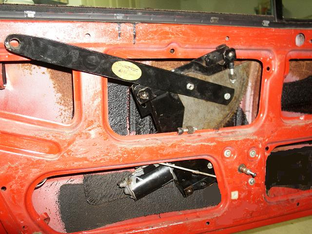
Pull the window pane to the top of the door frame and secure it in the fully closed position with the masking tape. Remove the regulator assembly through the middle top hole in the door frame.
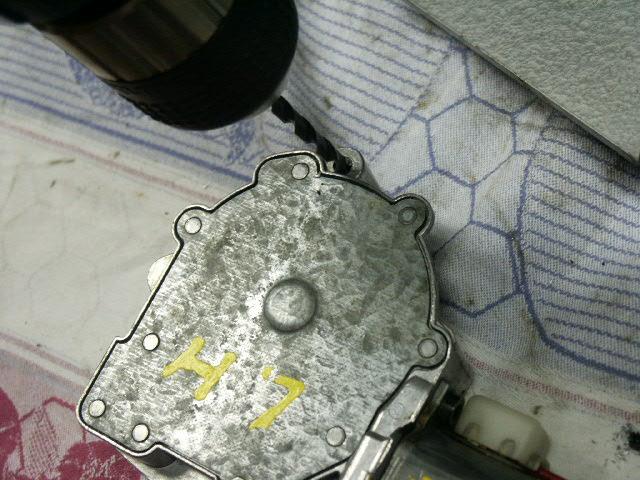
Step A3 - removal of the stock motor and associated gear boxes from the regulator
Important: The regulator window actuator arm will be spring loaded since the regulator assembly was removed with the regulator window actuator arm in the down position. Either hand crank the regulator to the window up position or secure the regulator before removing the gear box.
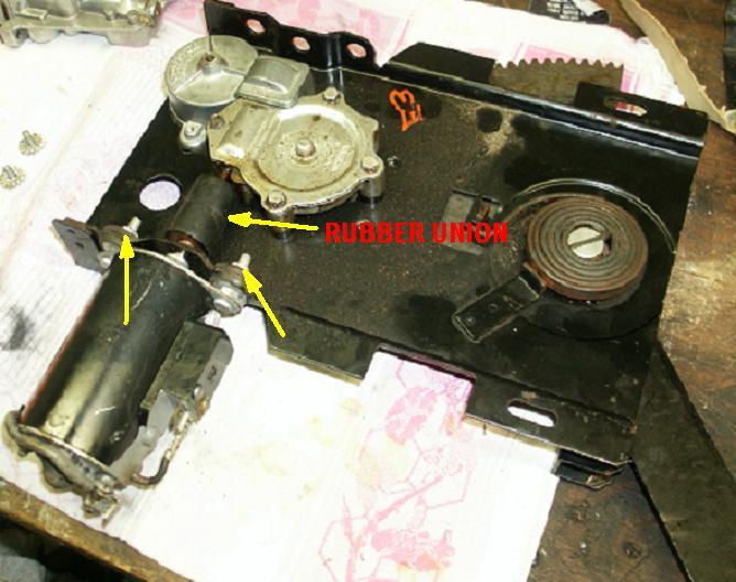
Remove the two (2) nuts/washers that secure the motor to the regulator using a 10 mm wrench or socket. Pull the motor free from the connecting rubber union and then remove the rubber union from the gear box.
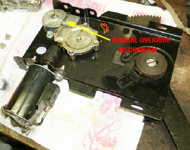
Remove the two (2) bolts that fasten the manual override mechanism to the regulator. Then remove the manual override mechanism, being careful not to lose the spring that disengages the manual override gear.
Insure that the regulator window actuator arm is either in the window "up" position or secured, then remove the three (3) bolts that fasten the gear box to the regulator using a 10 mm wrench or socket. Remove the gear box.
B - Modification and assembly of the regulator and the new motor
Note: If the motor hasn't been tested to insure it is working, do so now using a 12 volt power supply (battery, battery charger or some other power source). Verify the motor works in both the "up and down" directions by reversing the polarity, insuring there are no unusual noises or erratic operations noted.
Step B1 - adjusting the height of the mounts in the new motor/gear assembly
The height of the new motor mount stubs needs to be adjusted to properly engage the motor drive gear with the regulator window actuator arm gear. The drive gear of the motor should be engaged no less than the entire width of the regulator swing arm gear.
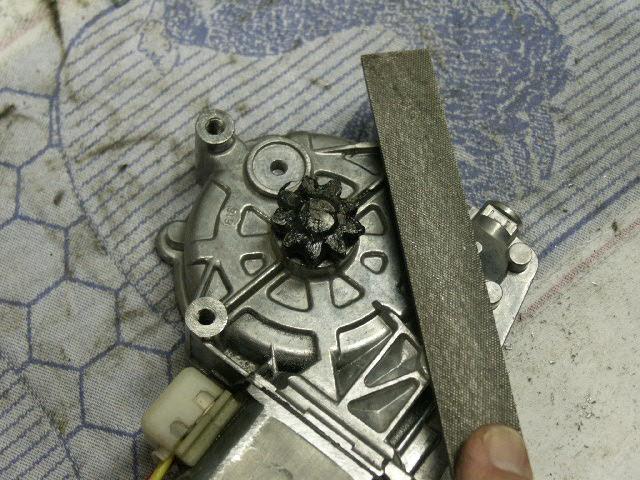
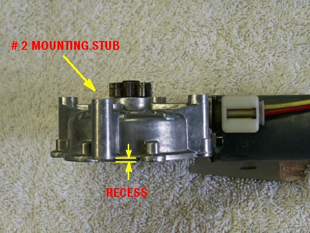
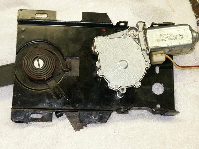
In the modification, the four mounting stubs of the new motor/gear, shown in the picture above, will be referred to as #1, 2, 3, and 4, starting with #1 at the motor and the rest in a clockwise fashion around the gear box. Note: mounting stub #2 is shorter than the rest and does not need to be adjusted. Also, references to the motor/gear box mating flange will be made.
Remember, on the passenger side the motor/gear assembly is a reverse image of the drivers side. All references made to the driver's side door installation will be reversed on the passenger side.
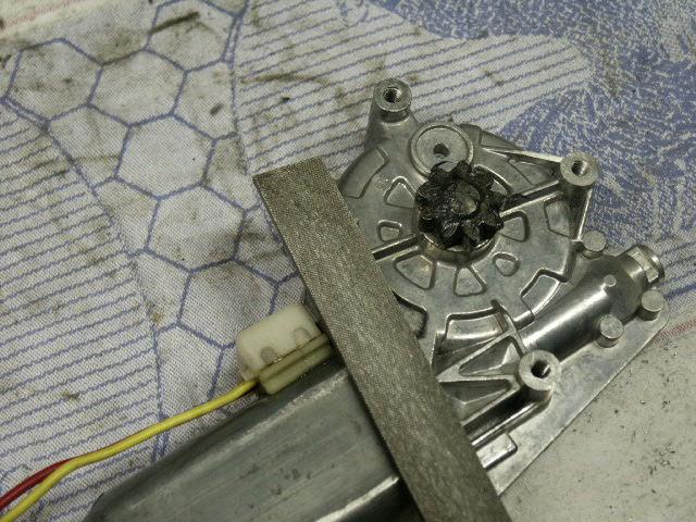
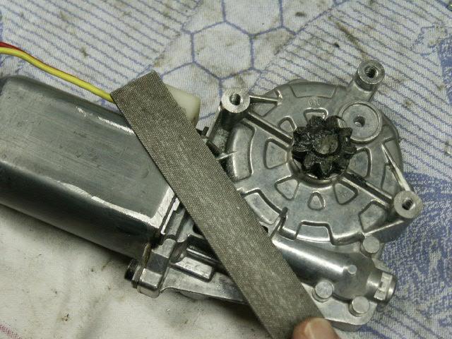
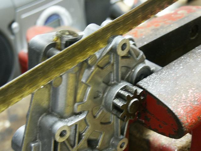
The gear side of the motor/gear will need to be lowered at least 0.004". Do this with iterative filing of the motor/gear box flange and mounting stubs as shown in the pictures above. Start with the motor and gear box mating flange, and work around the various mounting stubs, always keeping the file on two points at the same time.
Note: Only mounting stubs # 1, 3, and 4 will be adjusted. Mounting stub # 2, which will become the "primary" mounting stub, will not to be adjusted by filing it, since it was made shorter than the rest when it was manufactured. Mounting stub # 2 will need to be shimmed with a washer in the final assembly to make it match the height of mounting stubs # 1, 3, and 4.
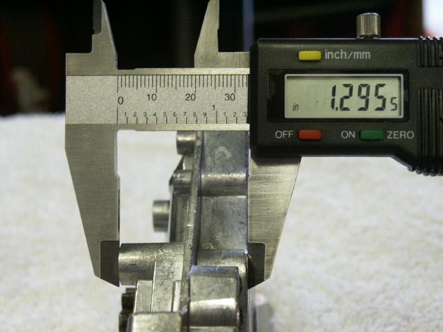
Check the height of the mounting stubs, as shown in the picture above. When you reach 1.295" you should be pretty close. After each series of filing the motor/gear mounting stubs, test mount the motor on the regulator and check to see how much of the motor/gear engages the regulator swing arm gear. Continue to file the motor/gear mounting stubs until you get the gears to fully engage.
Note: Since the # 2 mounting stub was made shorter than the others, the "fit" of the motor/gear to the regulator is done only with mounting stubs # 1, 3, 4 and the motor gear box mating flange.
Again, do not file mounting stubs # 1, 3, and 4 to enable mounting stub # 2 to mate directly with the regulator frame. Mounting stub # 2 will be shimmed to match the height of # 1, 3 and 4 stubs in the final assembly
Step B2 - Locating and drilling the new motor mount holes in the regulator and motor
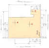
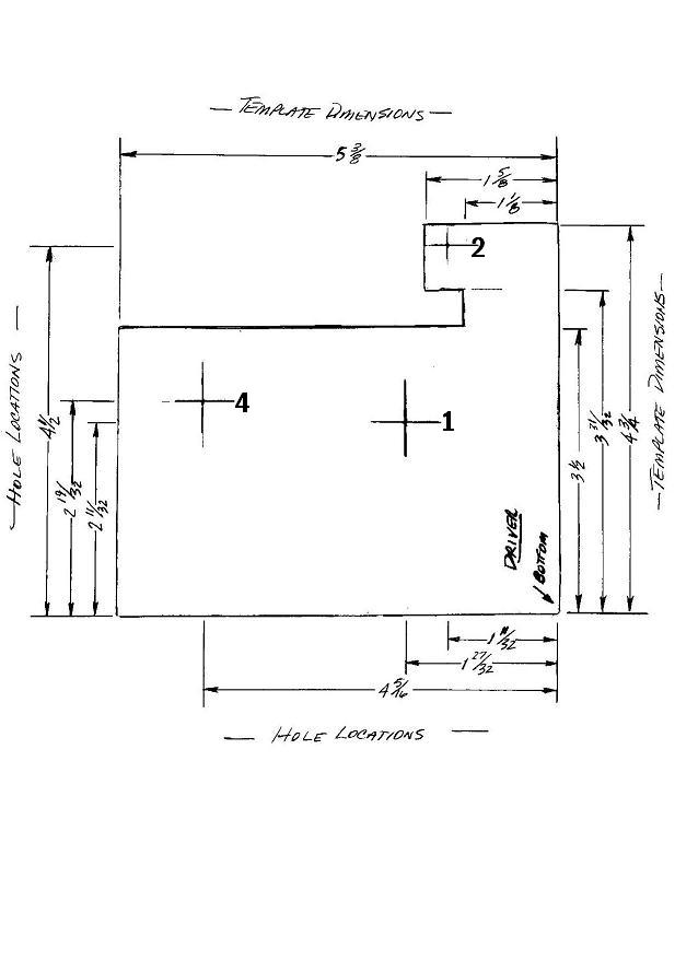
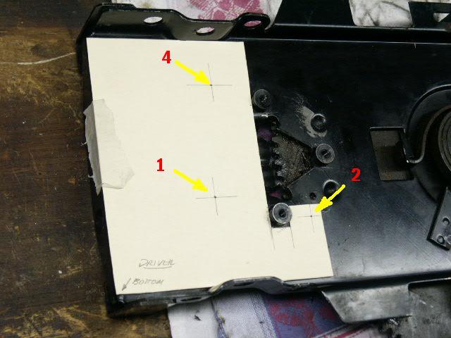
Only mounting stubs # 1, 2, and 4 will be used to secure the motor/gear to the regulator. The above pictures show two images of the template to locate the mounting bolt holes in the regulator. Print whichever template best suits your printer. Draw the template on a stiff piece of paper, such as a common manilla folder, using the dimensions shown. Cut out the template.
Locate the template as shown in the picture above, being careful to align the edge of the template with the edge of the regulator. Use a piece of tape to secure the template in place.
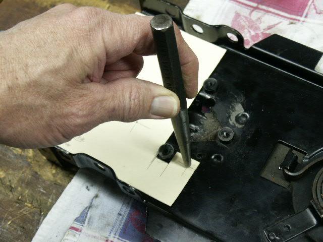
Using a center hole punch and a hammer, locate the mounting bolt hole locations as shown above, for mounting stubs # 1, 2, and 4. Mounting stub # 3 will not have a mounting bolt. Then remove and save the template. It will be used for the other door by flipping it over and doing the same procedure with that door.
Note: Since a large drill will tend to "ride" even with the indent created with the center hole punch, use a small drill bit (1/16" ) to create a larger pilot hole (do not go completely though the regulator) for each of the three holes you will finally drill in the regulator.
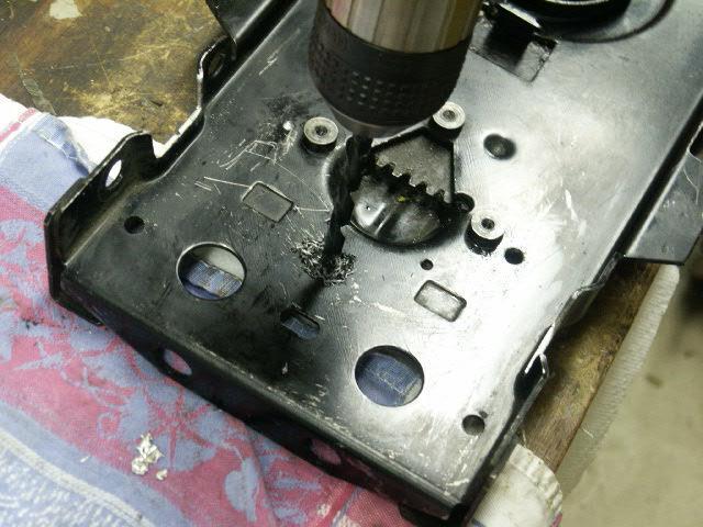
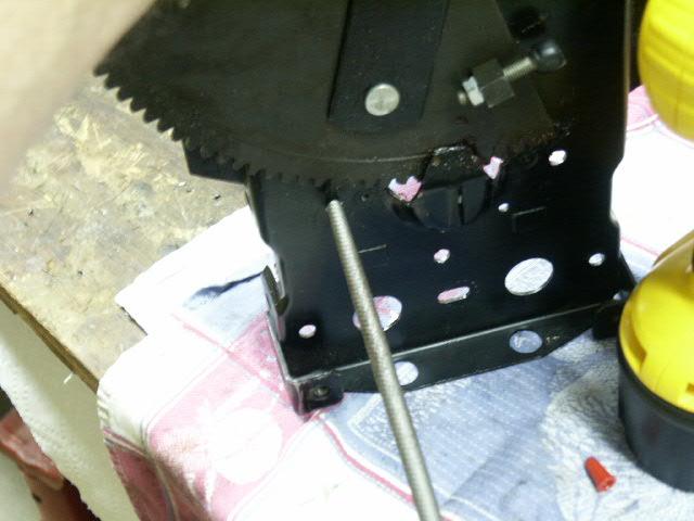
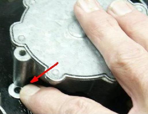
The above picture shows what the final position of the motor/gear on the regulator will be, with mounting stub # 2 of the motor gear highlighted. The "primary" motor mount hole in the regulator corresponding to mounting stub # 2 of the motor/gear will be drilled and tapped for the SAE 10-24 x 1-1/2" long bolt. Using a number 25 (0.150) drill bit, drill the 10-24 tap pilot hole, going through both the regulator frame and the regulator swing arm gear. This is done to allow the tap to completely thread the regulator frame.
Next using the SAE 10-24 tap, tap the hole through both the regulator frame and the regulator swing arm gear.
Note: Once installed the SAE 10-24 x 1-1/2" long bolt used in mounting stub # 2 will not go through the regulator swing arm gear.
Use a 1/4" drill bit to drill the # 1and 4 holes in the regulator. Use a round bastard file to clean any excess metal created by the drill on the face of the regulator.
Verify the proper location of mounting holes # 1 and 4 in the regulator by:
installing the # 2 "primary" mounting SAE 10-24 x 1-1/2" long bolt,
turning over the regulator while holding the motor in place,
checking the locations of the other two mounting hole locations for alignment, and
verifying that the SAE 12-24 bolts will fit through the regulator frame and screw into the motor/gear mounting holes.
When checking the alignment, insure that there is enough gear lash to prevent binding.
If the # 1 and 4 mounting stubs do not allow the 12-24 bolts to engage the motor mount holes, take a round bastard file as shown in the above picture and elongate them until they can.
The # 2 mounting stub on the motor/gear has an existing hole that goes completely through it. That hole must be increased in size to accommodate the SAE 10-24 bolt that will be used in this location. Using a 3/16" drill bit, ream out the hole.
Step B3 - Assembly and testing of the converted regulator assembly
Apply grease on the motor drive gear and the regulator swing arm. The picture above shows the passenger drive motor.
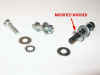
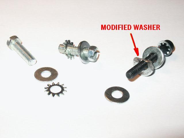
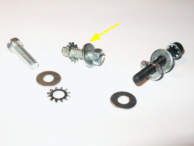
The motor/gear will be mounted to the regulator using three bolts, as shown in the first picture. The two SAE 12-24 x 9/16 long bolts will each need a washer and external lock washer. The # 2 "primary" mounting bolt, a SAE 10-24 x 1-1/2" long, will need three washers, two of them to act as "shims". Modify one of the washers by filing off one side so it will fill in the recess on the outside of the mounting stub (opposite the drive gear side as shown in the second picture above). The first picture above shows the modified washer in its position on the # 2 bolt.
The other "shim" washer is used to adjust for the short # 2 mounting stub on the gear side of the motor (see picture below), and insures a flush fit for the # 2 mounting stub so that it matches the height of the # 1 and 4 mounting stubs.
For the final assembly, place the motor/gear assembly on the regulator, locate the "shim" washer as shown in the above picture, and then install and hand tighten the SAE 10-24 x 1-1/2" long bolt with the lock washer, washer and modified "shim".
Install the SAE 12-24 x 9/16" long mounting bolts from the opposite side of the regulator with the external star washer and washer sequenced as shown above. The external star washer is installed next to the regulator frame and under the washer to "lock" the motor/gear in place on the regulator. Before these bolts are tightened, check the gear lash and insure that there is a very small amount of "play". Next, tighten all the mounting bolts.

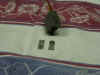
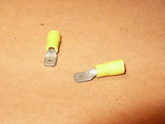
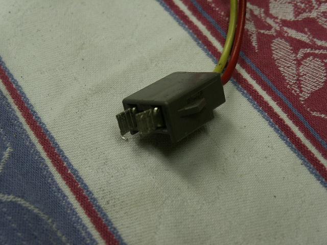
Two electrical unions need to be fabricated to provide a bridge from the female electrical connector on the motor/gear to the female electric connectors in the door. In the example shown in pictures above, two standard electrical 0.250" x 0.032" male disconnects (first picture) were modified first by pulling off their plastic protective shields, and then flattening the exposed ends to match the 0.250" width of the other end as shown in the second picture. Install them in the motor/gear connector as shown in the third picture.
Testing the New Regulator Assembly
In bench testing the converted regulator assembly, remember two important facts:
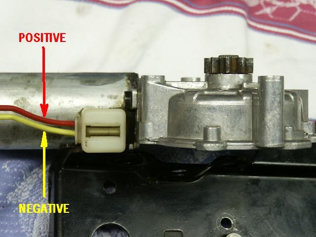
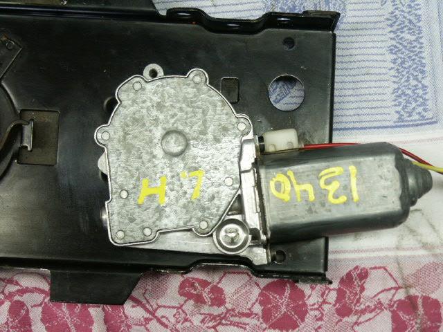
1 - The "red" lead on the motor is "positive" and the "yellow" lead is "negative", as shown in the picture above.
2 - When applying power to the motor, "positive" to "positive" on the motor makes the window go "up". Conversely by reversing the polarity, "positive" to "negative" on the motor makes the window go "down".
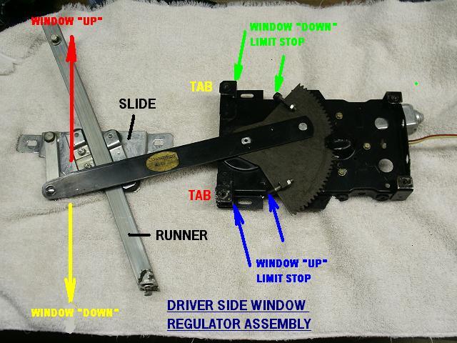
After installing the new window motor on the regulator, the regulator window actuator arm should be in the "window closed" or fully up position as shown by the above picture. In this position, test the regulator assembly by applying a "positive" power supply lead to the "negative" motor lead to make the window actuator arm go down. (The power supply negative lead is attached to the opposite motor lead).
Warning - Applying power to the motor with the wrong polarity will severely damage the regulator. If the new motor/gear is energized with the wrong polarity with the regulator window actuator arm at the full extent of its travel (on or near the regulator mounting tabs that provide a limit stop for the window actuator arm) , the window actuator arm will "run" through the unsupported regulator mounting tabs. These mounting tabs act as the window up and down limit stops. They are not supported until the regulator is installed in the door and these tabs are secured by the regulator mounting bolts.
As the last step in bench testing the regulator assembly, leave the window actuator arm in a slightly "open" position. This will facilitate attaching the window slide to the window pane once the slide/runner assembly is installed in the door.
C - Reassembly of the window mechanism in the door
Step C1 - Installation of the regulator and window runner
The installation of the converted regulator assembly will generally follow the disassembly process but in reverse order. Therefore, this section will only summarize that process but highlight several areas that will need specific attention.
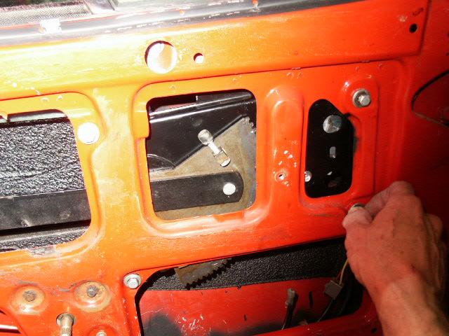
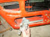
Insert the regulator assembly in the door as shown in the first picture above. Since the new motor is not in the way, this is a simple and easy process. Install and tighten the four mounting bolts.
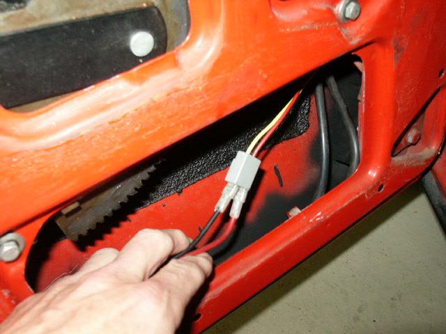
Attach the electrical connections. Before proceeding to the next step, operate the new window motor and verify that it is fully functional. Make sure the window pane is out of the way when operating the new motor.
Insert the window slide/runner assembly in the door as shown in the first picture. Reattach the window slide to the window pane and "loosely" fasten the two nuts that secure them together as shown in the second picture. Note: the window slide "bolt slot" in the second picture provides "front to back" space that may be used in the final "adjustment" of the window pane.
Fasten the window runner to the door frame with the two mounting bolts, each bolt with four washers - one at the head of the bolt and on the outside of the door frame, and three washers between the slide runner and the inside of the door frame (the number of internal washers on the two mounting bolts in your car may differ from the documented conversion). Align the two mounting holes of the window runner with those of the door, position the internal washers, and then screw in the mounting bolts, but only "hand" tight.
Note: Each of the two window runner fastening points will enable adjustment of the window pane travel path to eliminate or minimize binding of the window pane in the door window guide. The bottom fastening point of the window runner has side to side tolerance to enable adjustment of the window pane by loosening the bolt. The top fastening point provides for side to side adjustment by adding or subtracting one of the internal washers referred to above.
Step C2 - Adjustment of the window
As noted in the previous step there are three adjustment locations that may be used to align the window pane in the door window guide to eliminate or minimize binding of the window in the guide - the two window runner mounting points which provide side to side adjustment, and the window slide which provides front to back adjustment. At this point, the window slide/runner assembly should be "loosely" fastened to the door and window.
Be aware that the final adjustment of the window is an iterative process that strives to find a "happy medium" from "closed to open to close" operation of the window.
Slide the window up and down, correcting any obvious binding of the window pane in the window guides in the door by tweaking any of the three adjustment points. Once a "free flow" is obtained, tighten the two window runner mounting bolts and the two window slide bolts to a "snug" fit.
Next, reattach the regulator window actuator arm to the window slide pivot arm. Note: pay close attention to the sequence of the various washers that are used on the machine screw. The sequence should be: screw head, spring washer, regulator window actuator arm, plastic washer, steel washer, window slide pivot arm. The regulator window actuator arm should be able to turn freely on the window slide pivot arm bushing.
Final window conversion test
With the window regulator assembly completely assembled, use the window "flip" power switch and work the window up and down, again noting any binding of the window pane in the door window guide. Readjust the window again, this time using the window slide "front to back" adjustment in addition to the other adjustment points. Continue this process until a "happy medium" is reached. Tighten all the fasteners.
Step C3 - Reassembly of the upholstery panel and armrest
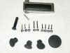
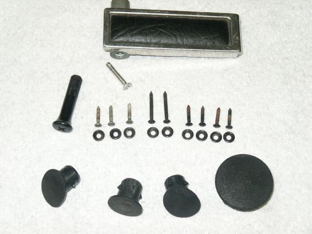
Aside from the arm rest and its screws and the upholstery panel, the picture above shows the items that you should have to complete the conversion process. There should be nine upholstery screws and washers.
Reattach the protective liner with masking tape. Try to align the existing arm rest and door handle bolt holes in the liner with the ones in the door.
Install the door handle, position the upholstery panel on the door, then attach the armrest using the large phillips head screwdriver.
Using the small phillips head screwdriver, install the nine upholstery panel screws with the upholstery washers. Remember, the two long screws are used for the two locations on the top of the panel. Install the door lock knob and you are done!
Alternative Conversion Options
Todd Reid's original conversion technique attaches the new motor in a different position on the regulator. Unlike the "hybrid" technique covered in detail above, Todd's original conversion technique requires a decision be made on whether the option of returning to the stock original motor is possible.
The "reversible" conversion leaves the option of remounting the original motor/gear on the regulator. The "one way" conversion does not allow the option of remounting the original motor/gear on the regulator. However, the removal and installation of the converted regulator assembly is the same for all conversion methods.
Reversible conversion
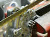
The "reversible" method requires additional modification of the # 3 motor mount stub and the gear housing ribs. This has to be done to clear the original regulator motor mounting lugs. This technique also requires that a small section of the regulator flange be removed. The pictures above show some of the detail of the conversion and the final regulator assembly.
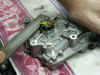
One Way Conversion
The "one way" conversion technique requires less modification to the new motor/gear and is the same as in the "hybrid" technique covered in detail above. This technique however requires the removal of the three original regulator motor mounting lugs as shown above. The motor can then be positioned in variety of positions on the regulator.